


 EAEU RU C-RU.PB98.V.00666/25
 EAEU N RU D-RU.RA07.V.76727/25
 ROSS RU.OS01.N00075/25
Saint Petersburg
Head office and production site
Telephone
Address
193149, Leningrad region, Vsevolozhsk district, Novosaratovka village, Rabochaya street, house 9, building 1

 Log in to your account
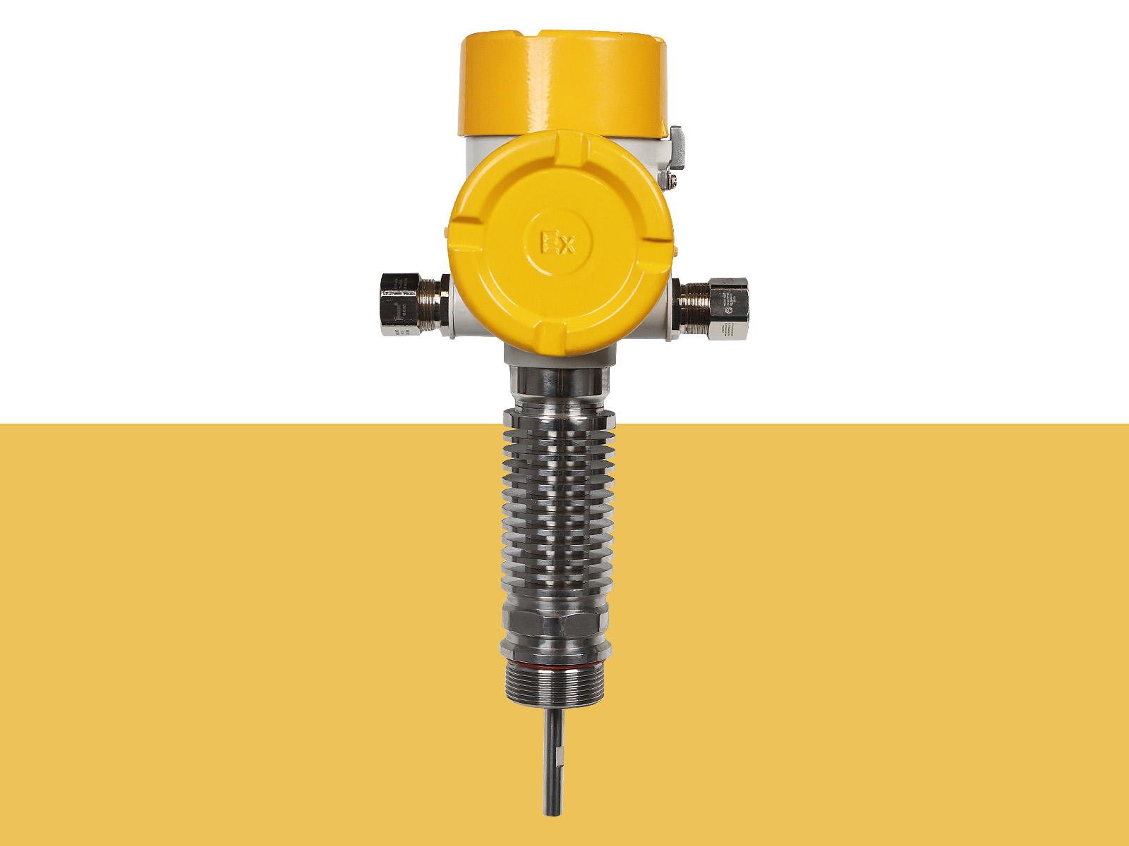
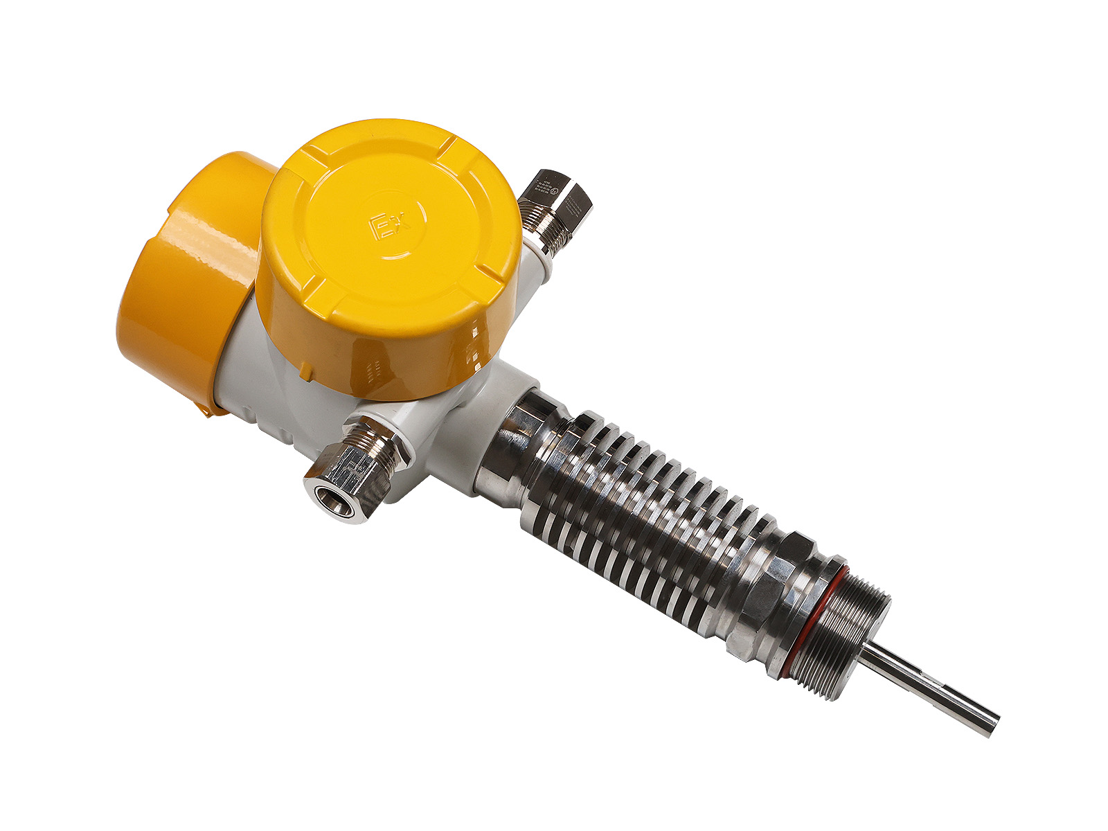
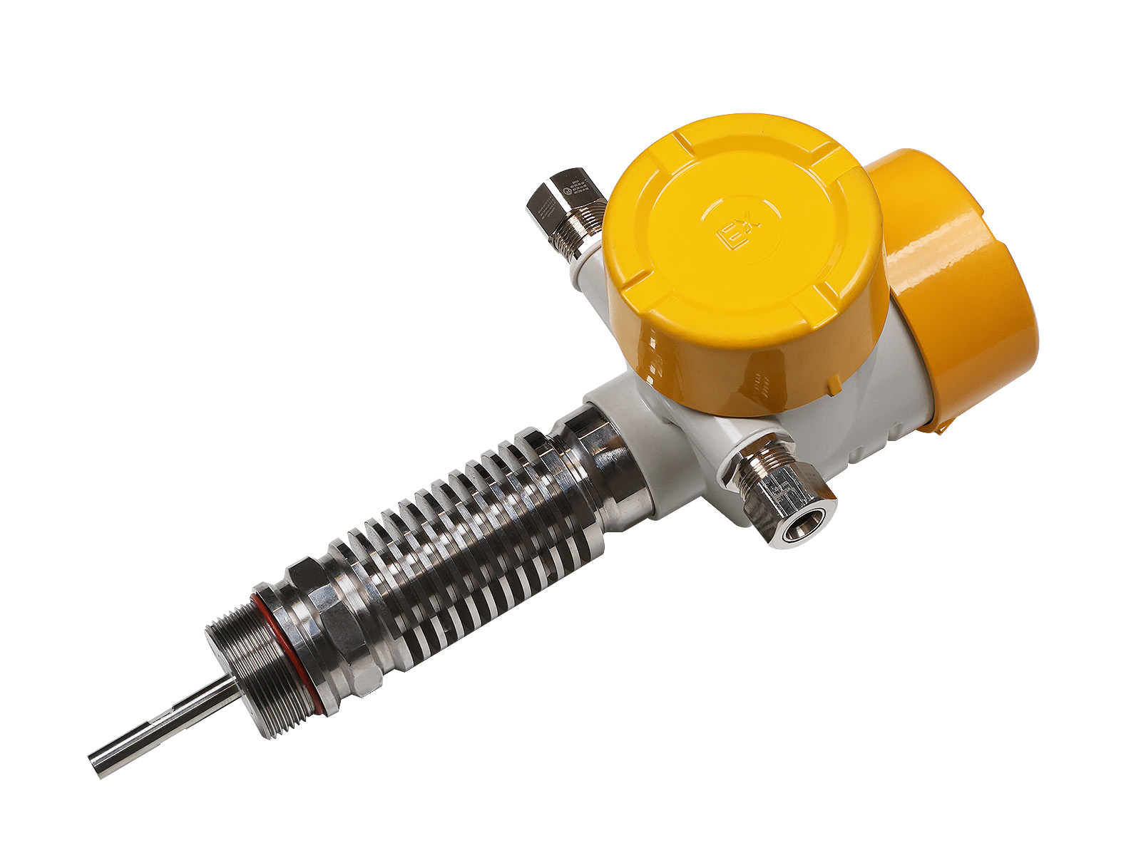
The GIP-1200 is a guided wave radar level transmitter using time-domain reflectometry (TDR) technology. It is designed to measure the level of liquids, pastes, granules, powders, and other bulk solids.
Application areas:
• Oil and gas, petrochemical and chemical industries.
• Nuclear industry.
• Mining and processing plants, pulp and paper mills, metallurgy, energy.
 1Ex db IIC T6…T1 Gb X 1Ex db IIC 450°С Gb X 0Ex ia IIC T6…T1 Ga X 0Ex ia IIC 450°С Ga X Ex tb IIIC T80°С…T440°С Db X Ex tb IIIC T450°С Db X Ex ia IIIC T80°С…T440°С Da X Ex ia IIIC T450°С Da X
 PB Ex db I Mb X PO Ex ia I Ma X
| Probe type | Flexible | Hard | Coaxial | HTHP Execution |
|---|---|---|---|---|
| Measurement range | 0-40 m. | 0-6 m. | ||
| Accuracy | ± 2 mm. (up to 6 meters) ± 3 mm. (at L 10 m. ± 0.03% of the measured value) |
|||
| Probe material | AISI 316L/C-276/Duplex 2205 (EN 1/4462) | |||
| Connection type | Thread/Flange | |||
| Temperature of the measured environment | -40…+180 °С (-40…+300 °С used with radiator) -60…+200 °С (-60…+300 °С used with radiator) -196…+260 °С (-196…+360 °С used with radiator) |
-196…+450 °C | ||
| Pressure of the measured medium | -0.1…4 MPa |
-0.1…40 MPa | ||
| Ambient temperature | -40…+85 °С (-61…+85 °С) | |||
| Output signal | 4-20 mA + HART; 4-20 mA + Relay 220 VAC 5A (4-wire circuit) RS-485 (Modbus); Profibus PA/DP; |
|||
| Indication | Display (built-in or external) LCD, OLED |
|||
| Configuration | HART communicator, HART modem + PC, Bluetooth, display | |||
| Cable entry | M20x1.5 or 1/2 NPT | |||
| Enclosure material | Aluminum alloy/Stainless steel | |||
| Nutrition | 9…40 VDC or 210…250 VAC | |||
| X1-X2-X3-X4-X5-X6-X7-X8-X9-X10-X11-X12-X13-X14-X15-X16/X17-X18-X19-X20-X21-X22-X23-X24-X25-X26-X27-X28 X1-X16 mandatory options |
||||||
|---|---|---|---|---|---|---|
| X1 | GIP-1200 | |||||
| - | Output signal type | |||||
| X2 | H2 | 4-20 mA with HART (2-wire) | ||||
| H4 | 4-20 mA with HART (4-wire) | |||||
| M | RS-485 Modbus (4-wire circuit) | |||||
| P2 | Profibus PA (2-wire) | |||||
| P4 | Profibus DP (4-wire) | |||||
| - | Explosion protection design | |||||
| X3 | ABOUT | General industrial | ||||
| IN | Explosion-proof (dust-proof) enclosure | |||||
| AND | Intrinsically safe electrical circuit | |||||
| - | Material and design of the case | |||||
| X4 | A1 | Single-section aluminum | ||||
| A2 | Two-piece aluminum | |||||
| H1 | Stainless steel single section | |||||
| H2 | Stainless steel two-piece | |||||
| - | Method of mounting the electronic unit | |||||
| X5 | AND | Integral | ||||
| U | Remote | |||||
| - | Distance between the electronic unit and the probe | |||||
| X6 | XX | Length of cable connecting the probe and the electronics unit, m | ||||
| 00 | for integral mounting | |||||
| - | Measurement error | |||||
| X7 | 1 | ± 1 mm | ||||
| 2 | ± 2 mm | |||||
| 3 | ± 3 mm | |||||
| 0 | ± 3.5 mm | |||||
| 5 | ± 5 mm | |||||
| 6 | ± 6 mm | |||||
| 10 | ± 10 mm | |||||
| - | Range: temperatures (pressures) of the technological process: | |||||
| X8 | N | -40…+180 °С; (-0.1…4 MPa) | ||||
| WITH | -60…+200 °С; (-0.1…4 MPa) | |||||
| IN | -196…+450 °С; (-0.1…40 MPa) | |||||
| - | Material of process connection and probe | |||||
| X9 | 01 | Stainless steel 08Х18Н10 (AISI 304) | ||||
| 02 | Stainless steel 03Х17Н13М2 (AISI 316L) | |||||
| 03 | Stainless steel 12X18H10T (AISI 321) | |||||
| 04 | Duplex stainless steel 02Х25Н22АМ2 (EN 1.4466/310 MoLN) | |||||
| 05 | Stainless steel ХН65МВ (Hastelloy C276) | |||||
| 20 | Stainless steel 08Х18Н10 (AISI 304) + with PTFE coating | |||||
| - | O-ring material: | |||||
| X10 | Tue | Ceramics + graphite (-200 … +500°C) | ||||
| K | TRUFLOUREZ T95 (-15 … +300°С) | |||||
| E | TRUFLOUREZ EPDM (-50 … +300°С) | |||||
| F | Viton Fluoroelastomer V7820 (-17 … +230°С) | |||||
| L | Viton Fluoroelastomer V7048 (-40 … +200°С) | |||||
| L1 | Viton Fluoroelastomer S5050 (-60 … +250°С) | |||||
| B | TRUFLOUREZ NBR (-40 … +120°С) | |||||
| FS | TRUFLOUREZ FVMQ (-60 … +230°С) | |||||
| - | Probe type | |||||
| X11 | G0 | Flexible | ||||
| Ж0 | Hard | |||||
| K0 | Coaxial | |||||
| Ж1 | Rigid with optional (DVC) L 300mm reference reflector | |||||
| K1 | Coaxial with optional (DVC) L 300mm reference reflector | |||||
| Ж2 | Rigid with optional (DVC) L 550mm reference reflector | |||||
| K2 | Coaxial with optional (DVC) L 550mm reference reflector | |||||
| - | Probe length | |||||
| X12 | XXXX | Probe length, cm | ||||
| - | Type of technological connection | |||||
| X13 | P1 | Thread 3/4 - 14 NPT | ||||
| P2 | Thread 1 - 11.5 NPT | |||||
| R3 | Thread 1 ½ - 11.5 NPT | |||||
| P4 | Thread G 3/4" | |||||
| P5 | Thread G 1" | |||||
| R6 | Thread G 1 ½" | |||||
| MK | Bracket mounting | |||||
| G1 | Flange GOST 33259.01 Steel flat welded flange | |||||
| G2 | Flange GOST 33259.02 Flat steel flange, loose, on a welded ring | |||||
| G3 | Flange GOST 33259.03 Flat steel flange, loose, on a flange | |||||
| G4 | Flange GOST 33259.04 Flat steel flange, loose, on a cluminaire for welding | |||||
| G5 | Flange GOST 33259.11 Steel butt-welded flange | |||||
| G6 | Flange GOST 33259. 21 Flange of the valve body | |||||
| E1 | Flange EN1092-1. 01 Flat weld flange | |||||
| E2 | Flange EN1092-1.02 Loose-fitting flat flange on a flat weld ring (type 32) or on a weld sleeve (type 33) | |||||
| E3 | Flange EN1092-1.04 Loose-fitting flat flange on butt weld ring (type 34) | |||||
| E4 | Flange EN1092-1.11 Welding neck flange | |||||
| E5 | Flange EN1092-1.12 Loose sleeve flange | |||||
| E6 | Flange EN1092-1.13 Threaded sleeve flange | |||||
| E7 | Flange EN1092-1.21 Non-removable flange (integral flange) | |||||
| A1 | ASME B16.5 flange. Flat welded. SO (Slip On) | |||||
| A2 | ASME B16.5 Welding Neck Flange (WN) | |||||
| A3 | ASME B16.5 Threaded Flange.TF (Threaded) | |||||
| A4 | ASME B16.5 Socket Weld Flange (SW) | |||||
| A5 | ASME B16.5 flange. Welded with overlap. LJ (Lapped) | |||||
| - | Size of technological connection | |||||
| X14 | XX | Without mounting flange | ||||
| 1 | DN50 | |||||
| 2 | DN80 | |||||
| 3 | DN100 | |||||
| 4 | DN150 | |||||
| - | Flange pressure | |||||
| X15 | XX | Without mounting flange | ||||
| G0 | PN6 (GOST) | |||||
| G1 | PN16 (GOST) | |||||
| G2 | PN25 (GOST) | |||||
| G3 | PN40 (GOST) | |||||
| G4 | PN63 (GOST) | |||||
| G5 | PN100 (GOST) | |||||
| G6 | PN160 (GOST) | |||||
| G7 | PN200 (GOST) | |||||
| G8 | PN250 (GOST) | |||||
| E0 | PN6 (EN1092-1) | |||||
| E1 | PN16 (EN1092-1) | |||||
| E2 | PN40 (EN1092-1) | |||||
| E3 | PN63 (EN1092-1) | |||||
| E4 | PN100 (EN1092-1) | |||||
| A0 | Class 150 (ASME) | |||||
| A1 | Class 300 (ASME) | |||||
| A2 | Class 600 (ASME) | |||||
| A3 | Class 900 (ASME) | |||||
| A4 | Class 1500 (ASME) | |||||
| A5 | Class 2500 (ASME) | |||||
| - | Design of the sealing surface | |||||
| X16 | XX | Without mounting flange | ||||
| 0G | GOST. Plane (A) | |||||
| 1G | GOST. Connecting projection (B) | |||||
| 2G | GOST. Spike (C) | |||||
| 3G | GOST. Tenon (L) | |||||
| 4G | GOST. Groove (D) | |||||
| 5G | GOST. Groove (M) | |||||
| 6G | GOST. Protrusion (E) | |||||
| 7G | GOST. Recess (F) | |||||
| 8G | GOST For oval gasket (J) | |||||
| 9G | GOST. Under the lens gasket (K) | |||||
| 0E | EN 1092-1. Flat surface (A) | |||||
| 1E | EN 1092-1. Raised connection B1 (PN2.5 - PN40) | |||||
| 2E | EN 1092-1. B2 connecting flange (PN63 - PN100) | |||||
| 3E | EN 1092-1. Tenon (C) | |||||
| 4E | EN 1092-1. Groove (D) | |||||
| 5E | EN 1092-1. Projection (E) | |||||
| 6E | EN 1092-1. Fold (F) | |||||
| 7E | EN 1092-1. Sealing ring boss (G) | |||||
| 8E | EN 1092-1. Sealing ring groove (H) | |||||
| 0A | ASME flat face flange (FF) | |||||
| 1A | ASME. Raised Face (RF) | |||||
| 2A | ASME. Large Ledge (LM) | |||||
| 3A | ASME. Small Protrusion (SM) | |||||
| 4A | ASME. Large Flange (LF) | |||||
| 5A | ASME. Small Notch (SF) | |||||
| 6A | ASME. Large Tenon (LT) | |||||
| 7A | ASME. Small Tenon (ST) | |||||
| 8A | ASME. Large Groove (LG) | |||||
| 9A | ASME. Small Groove (SG) | |||||
| AA | ASME. Oval Gasket Groove (RTG F) | |||||
| Additional options | ||||||
| - | Display installation method | |||||
| X17 | ||||||
| B0 | Built-in | |||||
| U0 | Remote (For 2-wire circuit) | |||||
| U1 | Remote (For 4-wire circuit) | |||||
| - | Display type | |||||
| X18 | ||||||
| D1 | LCD display with user interface (from -20 to + 85°C) | |||||
| D2 | OLED display with user interface (from -61 to + 85°C) | |||||
| D3 | TFT display with user interface (from -20 to + 70°C) | |||||
| - | Low-temperature design | |||||
| X19 | ||||||
| K1 | -51 °C ambient temperature | |||||
| K2 | -61 °C ambient temperature | |||||
| - | Additional output types | |||||
| X20 | ||||||
| P1 | 1 Relay output | |||||
| P2 | 2 Relay Outputs | |||||
| - | Probe diameter, mm | |||||
| X21 | ||||||
| XX | Specify the probe diameter in the range from 2 to 16 mm (specified if a non-standard diameter is required) | |||||
| - | Centering disc | |||||
| X22 | ||||||
| 02 | 2-in SST Centering Disc, 1.8 in. (45 mm) OD | |||||
| 03 | 3-in SST Centering Disc, 2.7 in. (68 mm) OD | |||||
| 04 | 4-in SST Centering Disc, 3.6 in. (92 mm) OD | |||||
| 06 | 6-in SST Centering Disc, 5.55 in. (141 mm) OD | |||||
| 22 | 2-in PTFE Centering Disc, 1.8 in. (45 mm) OD | |||||
| 23 | 3-in PTFE Centering Disc, 2.7 in. (68 mm) OD | |||||
| 24 | 4-in PTFE Centering Disc, 3.6 in. (92 mm) OD | |||||
| 26 | 6-in PTFE Centering Disc, 5.55 in. (141 mm) OD | |||||
| - | Additional metal plate | |||||
| X23 | ||||||
| MT | Additional marking plate (filled out at the customer’s request) | |||||
| - | Verification | |||||
| X24 | ||||||
| GP | Registration of a verification certificate on paper | |||||
| - | Configuring the device | |||||
| X25 | ||||||
| KO | Customizing the sensor according to the customer's request | |||||
| - | Certificates | |||||
| X26 | ||||||
| C1 | SIL Certificate | |||||
| - | Output signal standard | |||||
| X27 | ||||||
| H1 | NAMUR NE 43 | |||||
| H2 | NAMUR NE 107 | |||||
| - | Supply voltage | |||||
| X28 | ||||||
| AC | 220 AC | |||||
Drag files here
CAD " GORELTEX ", questionnaires, necessary documents
Head office and production site
Sales office
Sales office
Sales office and production site
Sales office
Sales office

