


 EAEU RU C-RU.PB98.V.00666/25
 EAEU N RU D-RU.RA07.V.76727/25
 ROSS RU.OS01.N00075/25
Saint Petersburg
Head office and production site
Telephone
Address
193149, Leningrad region, Vsevolozhsk district, Novosaratovka village, Rabochaya street, house 9, building 1

 Log in to your account
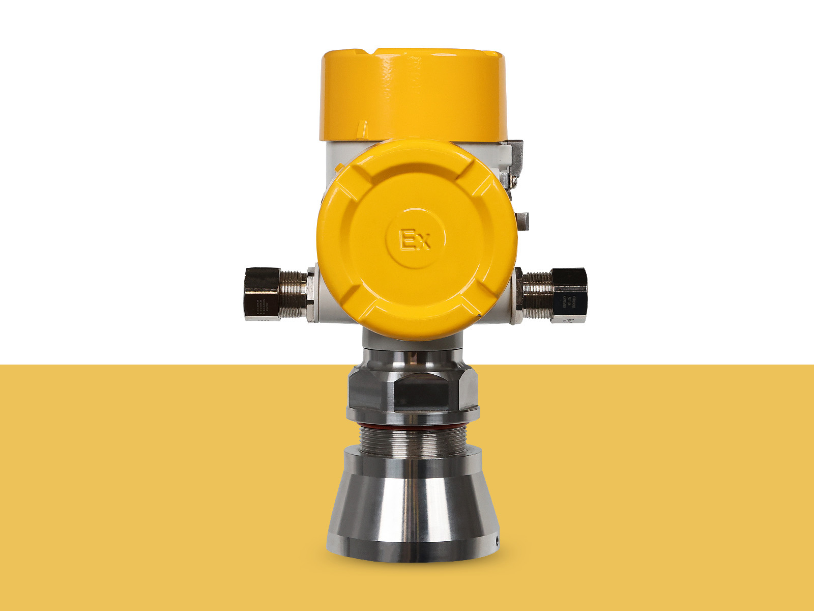
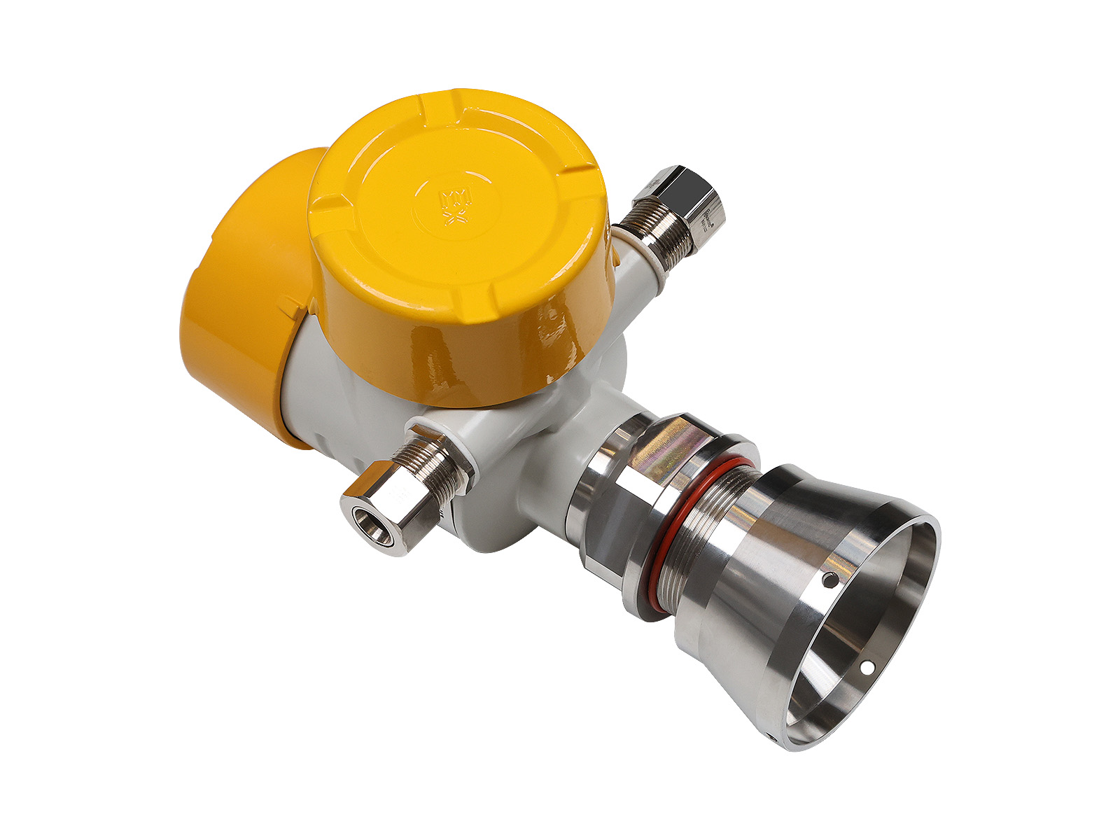
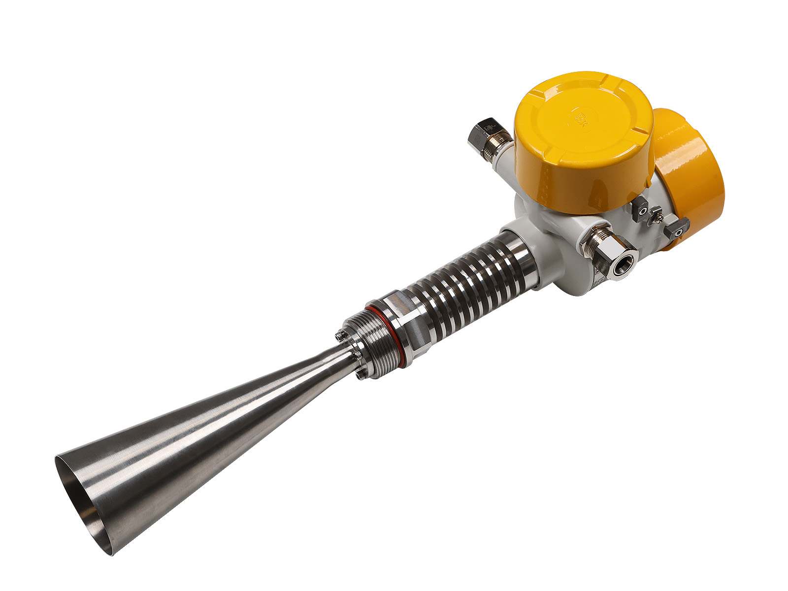
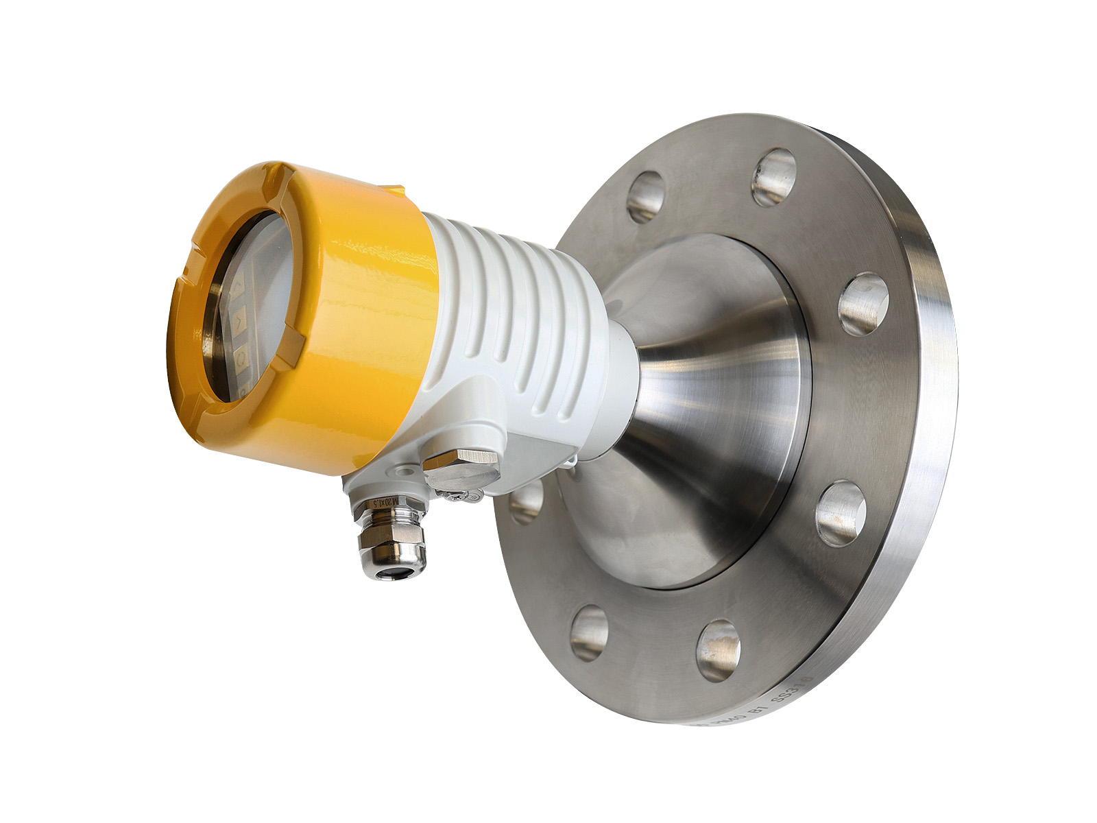
The GIP-1100 is a non-contact radar level meter using continuous frequency modulation wave (FMCW) technology. It is designed for continuous level measurement of liquids, pastes, granular, powdered, and other bulk materials in tanks, containers, and process equipment.
Application areas:
• Oil industry: monitoring the level of petroleum products in storage tanks.
• Chemical industry: monitoring the level of raw materials and components in columns, reactors, storage tanks.
• Mining: open and closed bunkers with dusty environments.
• Pulp and paper: tanks with chemical reagents, alkali, water.
• Food industry: containers and silos with finished product.
 1Ex db IIC T6…T1 Gb X 1Ex db IIC 450°С Gb X 0Ex ia IIC T6…T1 Ga X 0Ex ia IIC 450°С Ga X Ex tb IIIC T80°С…T440°С Db X Ex tb IIIC T450°С Db X Ex ia IIIC T80°С…T440°С Da X Ex ia IIIC T450°С Da X
 PB Ex db I Mb X PO Ex ia I Ma X
| Frequency | 26 GHz | 80 GHz | 120 GHz |
|---|---|---|---|
| Measurement range | 0-40 m. | 0-40 m. | 0-50 m. |
| Beam angle | 8° (DN 100) 10° (DN 80) 16° (DN 50) |
3° (DN 100) 4° (DN 80) 5° (DN 50) |
1° (DN 100) 4° (DN 50) |
| Antenna material | PTFE/PEEK | PTFE/PEEK Ceramics/Quartz Glass |
|
| Connection type | Threaded/Flange Flange with vent |
Threaded/Flange Flange with vent |
Threaded/Flange Flange with vent |
| Temperature of the measured environment | -40…+180 °С -60…+250 °С |
-40…+200°С -60…+300 °С |
-40…+200 °С -60…+480 °С |
| Pressure of the measured medium | -0.1…3.5 MPa |
-0.1…5 MPa |
-0.1…5 MPa -0.1…25 MPa |
| Ambient temperature | -40…+85 °С (-61…+85 °С) | ||
| Accuracy | ±1 mm (Max 10 m.) ±2 mm ±3 mm ±5 mm ±10 mm |
±1 mm ±2 mm ±3 mm ±5 mm ±10 mm |
|
| Output signal | 4-20 mA + HART; 4-20 mA + Relay 220 VAC 5A (4-wire circuit) RS-485 (Modbus); Profibus PA/DP; |
||
| Indication | Display (built-in or external) LCD, OLED |
||
| Configuration | HART communicator, HART modem + PC, Bluetooth, display | ||
| Cable entry | M20x1.5 or 1/2 NPT | ||
| Enclosure material | Aluminum alloy/Stainless steel | ||
| Nutrition | 9…40 VDC or 210…250 VAC | ||
| X1-X2-X3-X4-X5-X6-X7-X8-X9-X10-X11-X12-X13-X14-X15/X16-X17-X18-X19-X20-X21-X22-X23-X24-X25-X26 | ||||||
|---|---|---|---|---|---|---|
| Structure of the symbol | ||||||
| X1 | GIP-1100 | |||||
| - | Operating frequency | |||||
| X2 | 1 | 24 GHz | ||||
| 2 | 80 GHz | |||||
| 3 | 120 GHz | |||||
| 4 | 80 GHz (Circular Polarization) | |||||
| - | Version | |||||
| X3 | ABOUT | General industrial | ||||
| IN | Explosion-proof (dust-proof) enclosure | |||||
| AND | Intrinsically safe electrical circuit | |||||
| - | Material and design of the case | |||||
| X4 | A1 | Single-section aluminum alloy | ||||
| A2 | Two-piece aluminum alloy | |||||
| H1 | Stainless steel single section | |||||
| H2 | Stainless steel two-piece | |||||
| - | Output signal type | |||||
| X5 | H2 | 4-20 mA with HART (2-wire) | ||||
| H4 | 4-20 mA with HART (4-wire) | |||||
| M | RS-485 Modbus (4-wire circuit) | |||||
| P2 | Profibus PA (2-wire) | |||||
| P4 | Profibus DP (4-wire) | |||||
| - | Measurement error | |||||
| X6 | 1 | ± 1 mm | ||||
| 2 | ± 2 mm | |||||
| 3 | ± 3 mm | |||||
| 5 | ± 5 mm | |||||
| 10 | ± 10 mm | |||||
| - | Range | |||||
| X7 | D0 | 10 meters | ||||
| D1 | 15 meters | |||||
| D2 | 20 meters | |||||
| D3 | 30 meters | |||||
| D4 | 40 meters | |||||
| D5 | 50 meters | |||||
| - | Type of technological connection | |||||
| X8 | P1 | NPT conical thread | ||||
| P2 | Cylindrical pipe thread G | |||||
| R3 | Metric thread M | |||||
| MK | Bracket mounting | |||||
| G1 | Flange GOST 33259.01 Steel flat welded flange | |||||
| G2 | Flange GOST 33259.02 Flat steel flange, loose, on a welded ring | |||||
| G3 | Flange GOST 33259.03 Flat steel flange, loose, on a flange | |||||
| G4 | Flange GOST 33259.04 Flat steel flange, loose, on a cluminaire for welding | |||||
| G5 | Flange GOST 33259.11 Steel butt-welded flange | |||||
| G6 | Flange GOST 33259. 21 Flange of the valve body | |||||
| E1 | Flange EN1092-1. 01 Flat weld flange | |||||
| E2 | Flange EN1092-1.02 Loose-fitting flat flange on a flat weld ring (type 32) or on a weld sleeve (type 33) | |||||
| E3 | Flange EN1092-1.04 Loose-fitting flat flange on butt weld ring (type 34) | |||||
| E4 | Flange EN1092-1.11 Welding neck flange | |||||
| E5 | Flange EN1092-1.12 Loose sleeve flange | |||||
| E6 | Flange EN1092-1.13 Threaded sleeve flange | |||||
| E7 | Flange EN1092-1.21 Non-removable flange (integral flange) | |||||
| A1 | ASME B16.5 flange. Flat welded. SO (Slip On) | |||||
| A2 | ASME B16.5 Welding Neck Flange (WN) | |||||
| A3 | ASME B16.5 Threaded Flange.TF (Threaded) | |||||
| A4 | ASME B16.5 Socket Weld Flange (SW) | |||||
| A5 | ASME B16.5 flange. Welded with overlap. LJ (Lapped) | |||||
| - | Process connection material | |||||
| X9 | 01 | Stainless steel 08Х18Н10 (AISI 304) | ||||
| 02 | Stainless steel 03Х17Н13М2 (AISI 316L) | |||||
| 03 | Stainless steel 12X18H10T (AISI 321) | |||||
| 04 | Duplex stainless steel 02Х25Н22АМ2(EN 1.4466/310 MoLN) | |||||
| 05 | Stainless steel ХН65МВ (Hastelloy C276) | |||||
| 20 | Polytetrafluoroethylene (PTFE) | |||||
| 21 | Polyetheretherketone (PEEK) | |||||
| - | Process connection size (Thread/Flange) | |||||
| X10 | 24 GHz | |||||
| 1 | 1 ½"/- | |||||
| 2 | 2"/ DN50 | |||||
| 3 | 3"/ DN80 | |||||
| 4 | 4"/ DN100 | |||||
| 5 | 5"/DN125 | |||||
| 80 GHz | ||||||
| 1 | 1 ½"/DN32 | |||||
| 2 | 2 1/4"/DN50 | |||||
| 3 | 3 ½"/DN80 | |||||
| 4 | M128x2/DN100 | |||||
| 5 | М164х2.5/DN150 | |||||
| 6 | M220x2.5/DN200 | |||||
| 120 GHz | ||||||
| 1 | 3/4"/DN20 | |||||
| 2 | 1 ½"/DN32 | |||||
| 3 | M56x2/DN50 | |||||
| 4 | -/DN80 | |||||
| 5 | -/DN100 | |||||
| - | Flange pressure | |||||
| X11 | XX | Without mounting flange (indicated if one of the codes P1, P2, P3, MK is selected in item X8) |
||||
| GOST | ||||||
| G0 | PN6 | |||||
| G1 | PN16 | |||||
| G2 | PN25 | |||||
| G3 | PN40 | |||||
| G4 | PN63 | |||||
| G5 | PN100 | |||||
| G6 | PN160 | |||||
| G7 | PN200 | |||||
| G8 | PN250 | |||||
| EN | ||||||
| E0 | PN6 | |||||
| E1 | PN16 | |||||
| E2 | PN40 | |||||
| E3 | PN63 | |||||
| E4 | PN100 | |||||
| ASME | ||||||
| A0 | Class 150 | |||||
| A1 | Class 300 | |||||
| A2 | Class 600 | |||||
| A3 | Class 900 | |||||
| A4 | Class 1500 | |||||
| A5 | Class 2500 | |||||
| - | Design of the sealing surface | |||||
| X12 | XX | Without mounting flange (indicated if one of the codes P1, P2, P3, MK is selected in item X8) |
||||
| GOST | ||||||
| 0G | Plane (A) | |||||
| 1G | Connecting projection (B) | |||||
| 2G | Thorn (C) | |||||
| 3G | Spike (L) | |||||
| 4G | Groove (D) | |||||
| 5G | Groove (M) | |||||
| 6G | Ledge (E) | |||||
| 7G | Fault (F) | |||||
| 8G | For oval section gasket (J) | |||||
| 9G | Under the lens gasket (K) | |||||
| EN | ||||||
| 0E | Flat surface (A) | |||||
| 1E | Connecting ledge B1 (PN2.5 - PN40) | |||||
| 2E | Connecting lug B2 (PN63 - PN100) | |||||
| 3E | Thorn (C) | |||||
| 4E | Groove (D) | |||||
| 5E | Ledge (E) | |||||
| 6E | Fault (F) | |||||
| 7E | protrusion for the sealing ring (G) | |||||
| 8E | recess for sealing ring (H) | |||||
| ASME | ||||||
| 0A | Flat face flange (FF) | |||||
| 1A | Connecting flange (RF) | |||||
| 2A | Large Ledge (LM) | |||||
| 3A | Small protrusion (SM) | |||||
| 4A | Large Fault (LF) | |||||
| 5A | Small depression (SF) | |||||
| 6A | Large Thorn (LT) | |||||
| 7A | Small Thorn (ST) | |||||
| 8A | Large Groove (LG) | |||||
| 9A | Small groove (SG) | |||||
| AA | Oval section gasket recess (RTG F) | |||||
| - | Antenna type | |||||
| X13 | WITH | Rod | ||||
| R | Horn | |||||
| L | Lens | |||||
| - | Antenna seal material | |||||
| X14 | PT | Polytetrafluoroethylene (PTFE) | ||||
| PE | Polyetheretherketone (PEEK) | |||||
| KM | Ceramics | |||||
| KS | Quartz glass | |||||
| - | Nominal antenna size | |||||
| X15 | 24 GHz | |||||
| 1 | 1 ½" | |||||
| 2 | 2" | |||||
| 3 | 3" | |||||
| 4 | 4" | |||||
| 80 GHz | ||||||
| 1 | 1 ¼" | |||||
| 2 | 2" | |||||
| 3 | 3" | |||||
| 4 | 4" | |||||
| 120 GHz | ||||||
| 1 | 20 mm | |||||
| 2 | 35 mm | |||||
| 3 | 100 mm | |||||
| Additional options | ||||||
| / | Display installation method | |||||
| X16 | B0 | Built-in | ||||
| U0 | Remote (For 2-wire circuit) | |||||
| U1 | Remote (For 4-wire circuit) | |||||
| - | Display type | |||||
| X17 | D1 | LCD display with user interface (from -20 to + 85°C) | ||||
| D2 | OLED display with user interface (from -61 to + 85°C) | |||||
| D3 | TFT display with user interface (from -20 to + 70°C) | |||||
| - | Antennas | |||||
| X18 | A1 | Antenna with blow-through capability | ||||
| A2 | Antenna with articulated axis adjustment | |||||
| A3 | Anti-corrosion coating of surfaces in contact with the working environment | |||||
| A4 | Antenna with articulated axis adjustment + blowing | |||||
| - | Low-temperature design | |||||
| X19 | K1 | -51 °C ambient temperature | ||||
| K2 | -61 °C ambient temperature | |||||
| - | Additional output types | |||||
| X20 | P1 | 1 Relay output | ||||
| P2 | 2 Relay Outputs | |||||
| - | Additional metal plate | |||||
| X21 | MT | Additional marking plate (filled out at the customer’s request) | ||||
| - | Verification/calibration | |||||
| X22 | GP | Registration of a verification certificate in paper form | ||||
| - | Configuring the device | |||||
| X23 | KO | Customizing the sensor according to the customer's request | ||||
| - | Certificates | |||||
| X24 | C1 | SIL Certificate | ||||
| - | Output signal standard | |||||
| X25 | H1 | NAMUR NE 43 | ||||
| H2 | NAMUR NE 107 | |||||
| - | Supply voltage | |||||
| X26 | AC | 220 AC | ||||
Drag files here
CAD " GORELTEX ", questionnaires, necessary documents
Head office and production site
Sales office
Sales office
Sales office and production site
Sales office
Sales office

