


 EAEU RU C-RU.NA67.B.00778/25
 EAEU N RU D-RU.RA02.V.05658/26
 ROSS RU C-RU.MY62.V.00094/23
 Certificate No. 13-11.1-6.13.4-1656
 НСОПБ.RU.ЭО.ПР.111.Н.00245
 RU.OC BCCT 0222-04.2026
 OGN4.RU.1104.B04144
 GOST R ISO 9001-2015

Saint Petersburg
Head office and production site
Telephone
Address
193149, Leningrad region, Vsevolozhsk district, Novosaratovka village, Rabochaya street, house 9, building 1

 Log in to your account
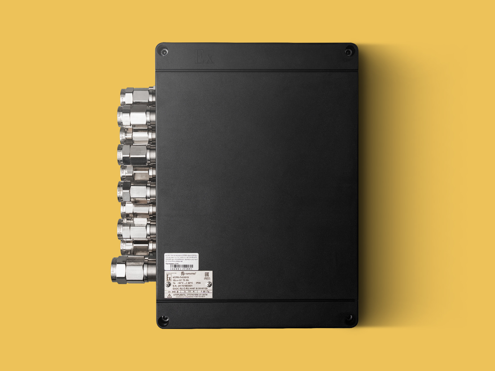
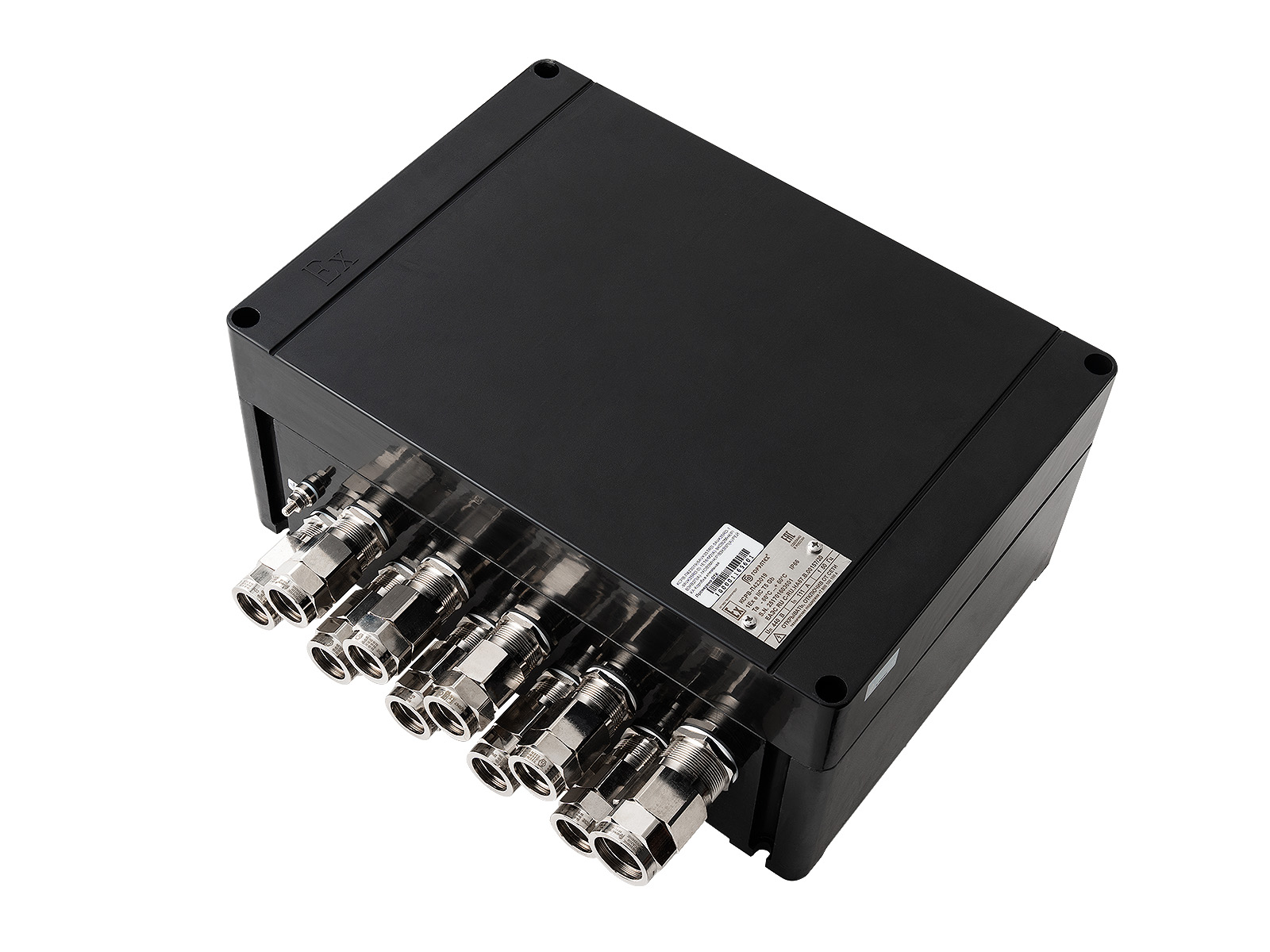
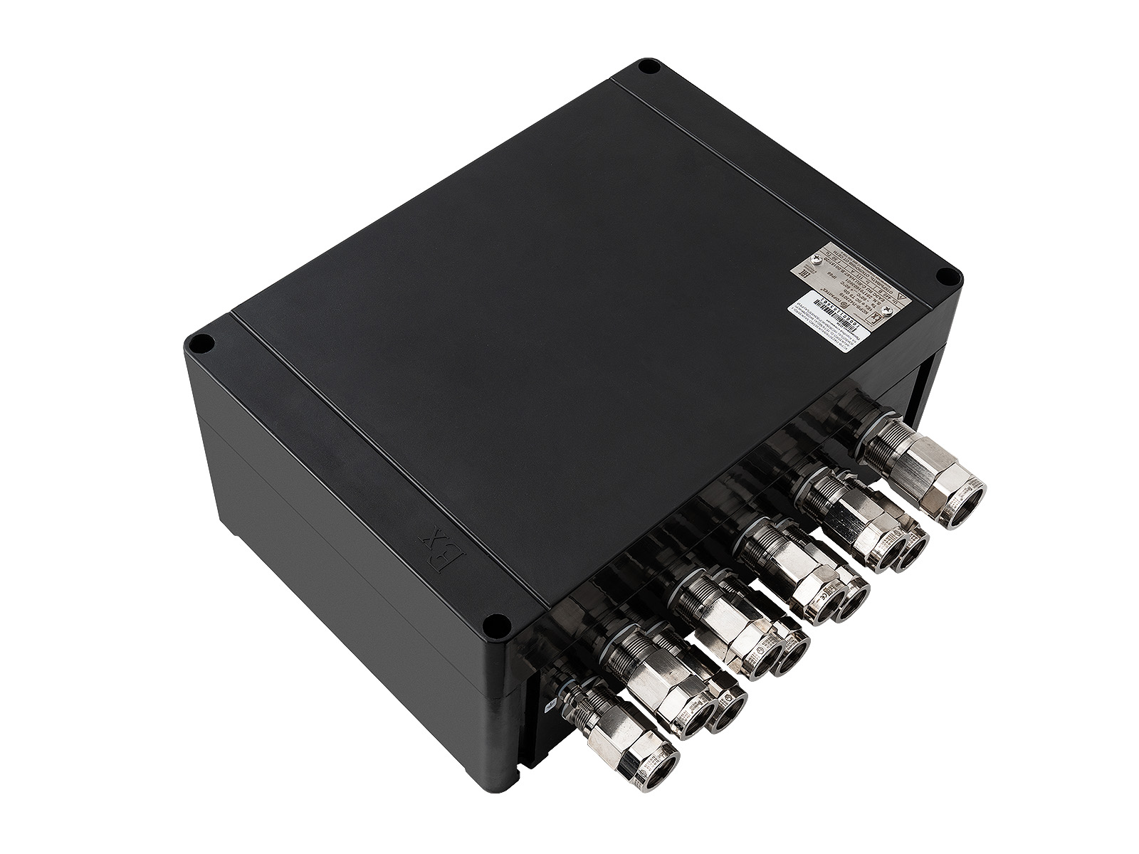
 TU 27.33.13-033-72453807-2017 TU 27.12.40-032-72453807-2017
 0Ex ia IIC T6...T4 Ga X 1Ex eb IIC T6...T4 Gb 1Ex ia IIC T6...T4 Gb Ex ib IIIC T85°...T135°С Db Ex tb IIIC T85°...T135°С Db 1Ex eb IIC T6...T4 Gb Ex tb IIIC T85°...T135°С Db Ex eb IIC Gb U Ex tb IIIC Db U
 RP Ex eb I Mc РВ Ex ib I Mb PO Ex ia I Ma RN1, RN2 Ex eb I Mc U


| Box size | Dimensions, mm | Weight, kg | ||||||||||
| A | B | C | D | d | E | I | D1 | d1 | E1 | E2 | ||
| KSRV-P100809 | 105 | 85 | 96 | 71 | 6,4 | 68 | - | 125 | 9 | - | - | 0,6 |
| KSRV-P141309 | 145 | 134 | 98 | 94 | 7 | 12 | - | 165 | 9 | - | - | 0,9 |
| KSRV-P161609 | 164 | 162 | 94 | 114 | 7 | 141 | - | 195 | 9 | - | - | 1,1 |
| KSRV-P170807 | 175 | 85 | 76 | 73 | 4,8 | 138 | - | - | 9 | 205 | - | 0,6 |
| KSRV-P170809 | 175 | 85 | 96 | 71 | 6,4 | 137 | - | - | 9 | 205 | - | 0,7 |
| KSRV-P211311 | 210 | 129,5 | 106,5 | 116 | 7 | 166 | - | - | 9 | 235 | - | 1,5 |
| KSRV-P221512 | 224,5 | 149,5 | 121 | 135 | 7 | 181 | - | 175 | 9 | 64 | - | 1,7 |
| KSRV-P221515 | 224,5 | 149,5 | 151 | 135 | 6,6 | 182 | - | 175 | 9 | 64 | - | 1,8 |
| KSRV-P261812 | 259,5 | 180 | 121 | 163,5 | 6 | 215,5 | - | 211 | 9 | 86 | - | 2,0 |
| KSRV-P302111* | 299 | 209 | 107 | 195 | 6,6 | 254 | - | 245 | 9 | 60 | - | 2,4 |
| KSRV-P302113 | 299 | 209 | 135 | 195 | 6,8 | 256 | - | 245 | 9 | 60 | - | 2,9 |
| KSRV-P332212* | 329,5 | 224 | 123 | 210 | 6,6 | 286 | - | 245 | 9 | 164 | - | 3,0 |
| KSRV-P332215 | 329,5 | 224 | 151 | 207 | 6,6 | 285 | - | 245 | 9 | 164 | - | 3,1 |
| KSRV-P362216 | 360 | 220 | 161,5 | 202 | 8,1 | 298,5 | - | 245 | 9 | 114 | - | 4,5 |
| KSRV-P363616 | 360 | 360 | 161,5 | 340 | 8,8 | 296 | - | 385 | 9 | 124 | - | 6,0 |
| KSRV-P423019 | 420 | 300 | 186 | 287,5 | 8,8 | 361 | - | 315 | 9 | 184 | - | 6,5 |
| KSRV-P723616 | 720 | 360 | 162 | 335 | 8,8 | 311 | 347 | 385 | 9 | 102 | 104 | 12,5 |
| KSRV-P723622 | 720 | 360 | 221,5 | 336 | 8,8 | 311 | 344 | 385 | 9 | 118 | 154 | 13,5 |
| KSRV-P723624 | 720 | 360 | 243 | 332 | 8,8 | 311 | 347 | 385 | 9 | 118 | 154 | 13,5 |
*Please contact a manager for availability and lead times for these sizes.
Overall and connection dimensions may vary slightly.


| Box size | Mounting panel* |
Mounting plate | |
| Part name |
Quantity per box, pcs. |
||
| KSRV-P100809 | KP1008X | - | - |
| KSRV-P141309 | - | - | - |
| KSRV-P161609 | - | - | - |
| KSRV-P170807 | KP1708X | A0154-01 | 2 |
| KSRV-P170809 | KP1708X | A0154-01 | 2 |
| KSRV-P211311 | KP2113X | - | - |
| KSRV-P221512 | KP2215X | A0154-02 | 2 |
| KSRV-P221515 | KP2215X | A0154-02 | 2 |
| KSRV-P261812 | KP2618X | A0154-03 | 2 |
| KSRV-P302111 | KP3021X | A0154-04 | 2 |
| KSRV-P302113 | KP3021X | A0154-04 | 2 |
| KSRV-P332212 | KP3322X | A0154-05 | 2 |
| KSRV-P332215 | KP3322X | A0154-05 | 2 |
| KSRV-P362216 | KP3622X | A0154-06 | 2 |
| KSRV-P363616 | KP3636X | A0154-07 | 2 |
| KSRV-P423019 | KP4230X | A0154-08 | 2 |
| KSRV-P723616 | KP7236X | A0154-08 | 2 |
| KSRV-P723622 | KP7236X | A0154-08 | 2 |
| KSRV-P723624 | KP7236X | A0154-08 | 2 |
Note: For the /BUS Z and /BUS H , the default configuration is buses with 2 x 16 mm2holes and a row of 6 mm2 holes( the number depends on the bus length). Busbars with different hole diameters can be installed upon agreement with the customer.
 IMPORTANT TO KNOW
When manufacturing explosion-proof boxes with hexagonal socket set screws, the screws must not protrude from the threaded hole after tightening the screw in accordance with GOST 30852.0-2002 (IEC 60079-0:1998) clause 9.3.3
| Cable entry size | Code | 01 | 1 | 2 | 3 | 4 | 5 | 6 | 7 | 8 | |
| G | 3/8” | 1/2” | 3/4” | 1” | 1 1/4” | 1 1/2” | 2” | 2 1/2” | 3” | ||
| M | M16X1.5 | M20X1.5 | M25X1.5 | M32X1.5 | M40X1.5 | M50X1.5 | M63X1.5 | M75X1.5 | M90X1.5 | ||
| KSRV-P100809 | A | G / M | 1/1 | 1/1 | 1/1 | - | - | - | - | - | - |
| B | G / M | 2/2 | 1/1 | 1/1 | 1/1 | - | - | - | - | - | |
| KSRV-P141309 | A | G / M | 4/4 | 4/4 | 2/2 | 1/1 | 1/1 | - | - | - | - |
| B | G / M | 5/5 | 3/3 | 2/2 | 1/1 | - | - | - | - | - | |
| KSRV-P161609 | A | G / M | 6/6 | 4/4 | 3/3 | 2/2 | - | - | - | - | - |
| B | G / M | 4/4 | 4/4 | 2/2 | 2/2 | - | - | - | - | - | |
| KSRV-P170807 | A | G / M | 3/3 | 3/3 | - | - | - | - | - | - | - |
| B | G / M | 1/1 | 1/1 | - | - | - | - | - | - | - | |
| KSRV-P170809 | A | G / M | 5/5 | 3/4 | 2/2 | 2/2 | - | - | - | - | - |
| B | G / M | 2/2 | 1/1 | 1/1 | 1/1 | - | - | - | - | - | |
| KSRV-P211311 | A | G / M | 7/7 | 5/5 | 3/3 | 3/3 | 2/2 | - | - | - | - |
| B | G / M | 6/6 | 4/4 | 2/2 | 1/1 | 1/1 | - | - | - | - | |
| KSRV-P221512 | A | G / M | 10/10 | 8/8 | 5/5 | 3/3 | 2/2 | 1/1 | - | - | - |
| B | G / M | 6/6 | 6/6 | 3/3 | 2/2 | 1/1 | 1/1 | - | - | - | |
| KSRV-P221515 | A | G / M | 15/15 | 12/12 | 6/6 | 6/6 | 2/3 | 2/2 | 1/1 | 1/1 | - |
| B | G / M | 10/10 | 9/9 | 5/5 | 4/4 | 2/2 | 1/1 | 1/1 | 1/1 | - | |
| KSRV-P261812 | A | G / M | 12/12 | 10/10 | 5/5 | 4/4 | 3/3 | 1/1 | - | - | - |
| B | G / M | 9/9 | 8/8 | 4/4 | 3/3 | 2/2 | 1/1 | - | - | - | |
| KSRV-302111 | A | G / M | 12/12 | 9/9 | 6/6 | 4/4 | 2/2 | - | - | - | - |
| B | G / M | 6/6 | 4/4 | 2/2 | 1/1 | 1/1 | - | - | - | - | |
| KSRV-P302113 | A | G / M | 12/12 | 9/9 | 6/6 | 4/4 | 2/2 | - | - | - | - |
| B | G / M | 10/10 | 8/8 | 4/4 | 3/3 | 2/2 | - | - | - | - | |
| KSRV-P332212 | A | G / M | 16/16 | 13/13 | 7/8 | 5/5 | 4/4 | 2/2 | - | - | - |
| B | G / M | 12/12 | 10/10 | 5/5 | 4/4 | 3/3 | 2/2 | - | - | - | |
| KSRV-P332215 | A | G / M | 27/27 | 21/21 | 12/12 | 10/10 | 5/5 | 3/3 | 3/3 | 2/2 | - |
| B | G / M | 18/18 | 15/15 | 9/9 | 6/6 | 4/4 | 2/2 | 2/2 | 1/1 | - | |
| KSRV-P362216 | A | G / M | 24/24 | 21/21 | 12/12 | 10/10 | 5/5 | 3/3 | 3/3 | 2/2 | - |
| B | G / M | 15/15 | 13/13 | 8/8 | 6/6 | 3/3 | 2/2 | 2/2 | 1/1 | - | |
| KSRV-P363616 | A | G / M | 27/27 | 21/21 | 14/14 | 10/10 | 6/6 | 4/4 | 3/3 | 2/2 | - |
| B | G / M | 33/33 | 27/27 | 16/16 | 12/12 | 7/7 | 4/4 | 3/3 | 3/3 | - | |
| KSRV-P423019 | A | G / M | 37/38 | 29/29 | 18/18 | 12/12 | 8/8 | 5/5 | 4/4 | 3/3 | 2/2 |
| B | G / M | 30/30 | 22/22 | 15/15 | 10/10 | 7/7 | 4/4 | 3/3 | 2/2 | 2/2 | |
| KSRV-P723616 | A | G / M | 48/48 | 39/39 | 24/24 | 18/18 | 11/11 | 6/6 | 5/5 | 4/4 | - |
| B | G / M | 30/30 | 27/27 | 16/16 | 12/12 | 7/7 | 4/4 | 3/3 | 3/3 | - | |
| KSRV-P723622 | A | G / M | 92/92 | 72/72 | 46/46 | 30/30 | 22/22 | 14/14 | 12/12 | 6/6 | 4/4 |
| B | G / M | 51/51 | 40/40 | 26/26 | 18/18 | 12/12 | 8/8 | 6/6 | 3/3 | 2/2 | |
| KSRV-P723624 | A | G / M | 92/92 | 75/75 | 46/46 | 30/30 | 22/22 | 14/14 | 12/12 | 6/6 | 4/4 |
| B | G / M | 51/51 | 43/43 | 26/26 | 18/18 | 12/12 | 8/8 | 6/6 | 3/3 | 2/2 | |
| Box size | Number of terminals/nominal wire cross-section, mm2 | ||
| 1,5 | 2,5 | 4 | |
| KSRV-P100809 | 12 | 10 | 8 |
| KSRV-P141309 | 20 | 16 | |
| KSRV-P161609 | 23 | 19 | |
| KSRV-P170807 | 28 | 24 | 19 |
| KSRV-P170809 | 28 | 24 | 19 |
| Box size | Maximum number of terminals (maximum number of terminals in one row)/nominal wire cross-section, mm2 | ||||||||||
| 2,5 | 4 | 6 | 10 | 16 | 35 | 50N | 70 | 95 | 150 | 240 | |
| KSRV-P100809 | 5 | 4 | - | - | - | - | - | - | - | - | - |
| KSRV-P141309 | 21 | 18 | 13 | 10 | 9 | 6 | - | - | - | - | - |
| KSRV-P161609 | 25 | 34(21) | 16 | 12 | 10 | 8 | - | - | - | - | - |
| KSRV-P170809 | 22 | 18 | 14 | 10 | 7 | 5 | - | - | - | - | - |
| KSRV-P211311 | 32 | 27 | 21 | 17 | 14 | 10 | 5 | - | - | - | - |
| KSRV-P221512 | 34 | 28 | 22 | 17 | 14 | 11 | 5 | - | - | - | - |
| KSRV-P221515 | 34 | 28 | 22 | 17 | 14 | 11 | 5 | - | - | - | - |
| KSRV-P231513 | 48(38) | 40(32) | 30(24) | 19 | 16 | 12 | 6 | - | - | - | - |
| KSRV-P261812 | 86(43) | 72(36) | 54(27) | 26(21) | 20(18) | 15 | 11 | 5 | - | - | - |
| KSRV-P302111 | 100(50) | 82(42) | 64(32) | 42(25) | 25(21) | 16 | 13 | - | - | - | - |
| KSRV-P302113 | 100(50) | 82(42) | 64(32) | 42(25) | 25(21) | 16 | 13 | 7 | - | - | - |
| KSRV-P332212 | 108(54) | 90(45) | 70(35) | 54(28) | 28(23) | 20(17) | 15 | 8 | - | - | - |
| KSRV-P332215 | 108(54) | 90(45) | 70(35) | 54(28) | 28(23) | 20(17) | 15 | 8 | - | - | - |
| KSRV-P362216 | 94(54) | 78(45) | 60(35) | 32(28) | 28(23) | 20(17) | 16 | 8 | - | - | - |
| KSRV-P363616 | 193(63) | 160(52) | 120(39) | 76(31) | 63(26) | 45(19) | 15 | 14 | 12 | 10 | - |
| KSRV-P423019 | 222(74) | 186(62) | 138(46) | 88(37) | 62(31) | 46(23) | 22(18) | 17 | 14 | 8 | 7 |
| KSRV-P723616 | 260(130) | 218(109) | 168(84) | 134(67) | 110(55) | 82(41) | 44(36) | 32 | 8 | 7 | - |
| KSRV-P723622 | 268(134) | 224(112) | 168(84) | 134(67) | 112(56) | 84(42) | 33 | 30 | 26 | 18 | 10 |
| KSRV-P723624 | 260(130) | 218(109) | 168(84) | 134(67) | 110(55) | 82(41) | 44(36) | 32 | 8 | 7 | - |
| Box size | Components with type of protection "Ex de" |
| KSRV-P100809 | 1 |
| KSRV-P141309 | 3 |
| KSRV-P170809 | 3 |
| KSRV-P161609 | 4 |
| KSRV-P211311 | 5 |
| KSRV-P221512 | 6 |
| KSRV-P221515 | 6 |
| KSRV-P261812 | 9 |
| KSRV-P302111 | 10 |
| KSRV-P302113 | 10 |
| KSRV-P332212 | 16 |
| KSRV-P332215 | 16 |
| KSRV-P362216 | 16 |
| KSRV-P363616 | 28 |
| KSRV-P423019 | 25 |
| KSRV-P723616 | 45 |
| KSRV-P723622 | 45 |
| KSRV-P723624 | 45 |
*The number of installed elements depends on their dimensions and contact group sizes. The exact number of elements and housing size for a specific solution are specified when ordering.
Drag files here
CAD " GORELTEX ", questionnaires, necessary documents

Example: KSRV-P161609 (20C2-4C10-1PE10)-2KNV1N(B)-1KOV3N(A)-2KOV3N(V)-TU 27.33.13-033-72453807-2017
If you have difficulty choosing the box size based on the required characteristics, put the letter X instead of numbers after the box name.
Example: KSRV-P X (20C2-4C10-1PE10)-2KNV1N(B)-1KOV3N(A)-2KOV3N(V)-TU 27.33.13-033-72453807-2017
Head office and production site
Sales office
Sales office
Sales office and production site
Sales office
Sales office

