


Saint Petersburg
Head office and production site
Telephone
Address
193149, Leningrad region, Vsevolozhsk district, Novosaratovka village, Rabochaya street, house 9, building 1

 Log in to your account
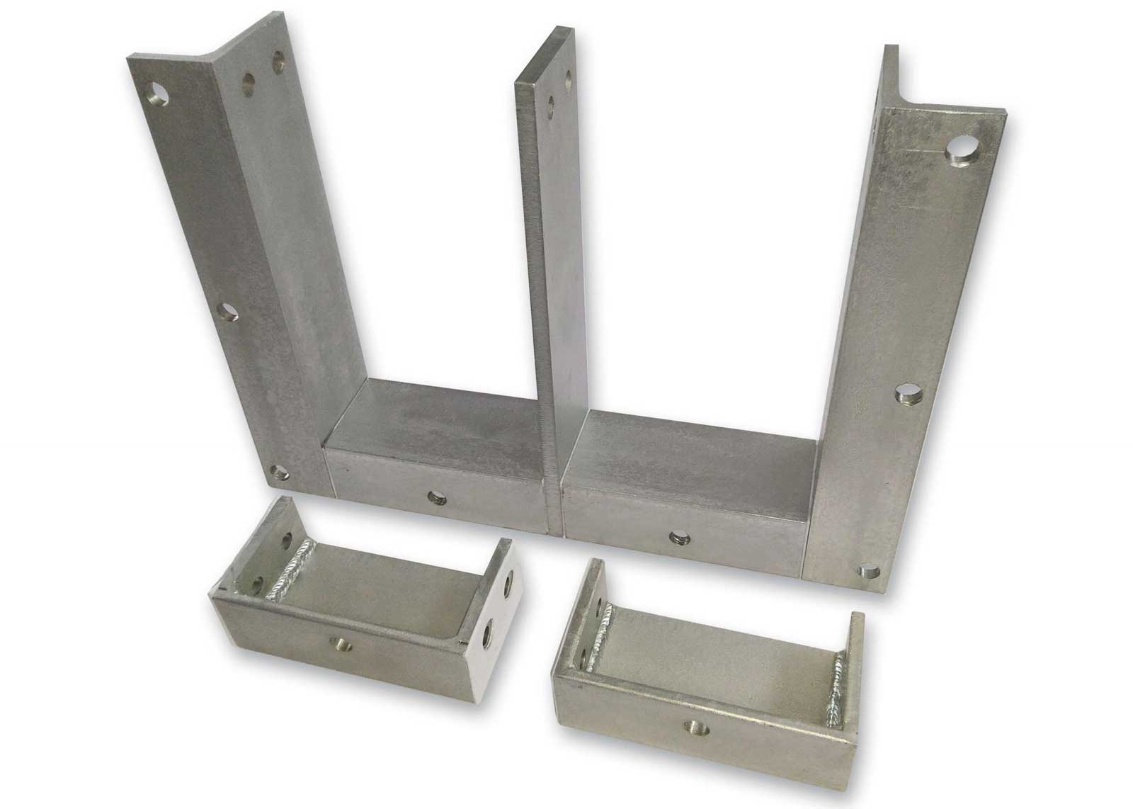
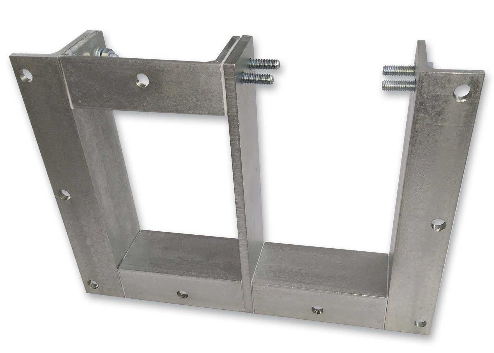
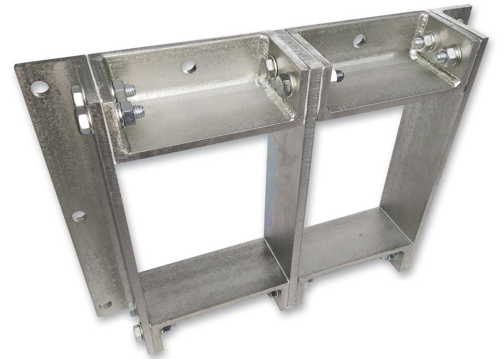
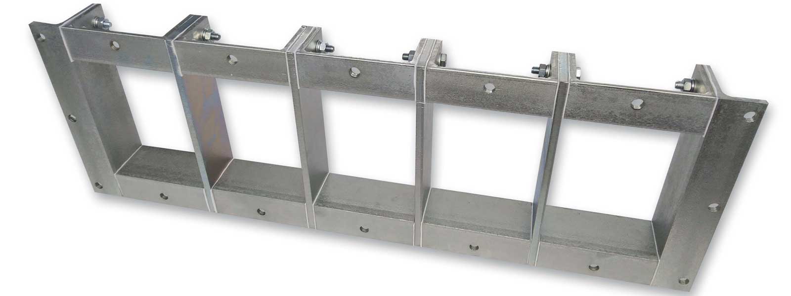
 1Ex e IIC Gb Ex tb IIIC Db
 RP Ex e I Mc

| Marking of mounting frames | Number of compartments | Dimensions of the sealing section, mm | Steel thickness, mm | Columns | Rows | Partition thickness | External frame dimensions, mm | Size of the mounting opening in the wall, mm | Upper flange + lower flange = right flange + left flange | |||
|---|---|---|---|---|---|---|---|---|---|---|---|---|
| l | h | L | H | Shire | High | |||||||
| NTM-RMR10.1x1/KPG | 1 | 120 | 101 | 6 | 1 | 1 | 8 | 200 | 181 | 124 | 105 | 80 |
| NTM-RMR10.2x1/KPG | 2 | 120 | 101 | 6 | 2 | 1 | 8 | 328 | 181 | 252 | 105 | 80 |
| NTM-RMR10.3x1/KPG | 3 | 120 | 101 | 6 | 3 | 1 | 8 | 456 | 181 | 380 | 105 | 80 |
| NTM-RMR10.4x1/KPG | 4 | 120 | 101 | 6 | 4 | 1 | 8 | 584 | 181 | 508 | 105 | 80 |
| NTM-RMR10.5x1/KPG | 5 | 120 | 101 | 6 | 5 | 1 | 8 | 712 | 181 | 636 | 105 | 80 |
| NTM-RMR10.6x1/KPG | 6 | 120 | 101 | 6 | 6 | 1 | 8 | 840 | 181 | 764 | 105 | 80 |
| NTM-RMR10.7x1/KPG | 7 | 120 | 101 | 6 | 7 | 1 | 8 | 968 | 181 | 892 | 105 | 80 |
| NTM-RMR10.8x1/KPG | 8 | 120 | 101 | 6 | 8 | 1 | 8 | 1096 | 181 | 1020 | 105 | 80 |
| NTM-RMR10.9x1/KPG | 9 | 120 | 101 | 6 | 9 | 1 | 8 | 1224 | 181 | 1148 | 105 | 80 |
| NTM-RMR10.10x1/KPG | 10 | 120 | 101 | 6 | 10 | 1 | 8 | 1352 | 181 | 1276 | 105 | 80 |
| NTM-RMR10.1x2/KPG | 2 | 120 | 101 | 6 | 1 | 2 | 8 | 200 | 290 | 124 | 214 | 80 |
| NTM-RMR10.2x2/KPG | 4 | 120 | 101 | 6 | 2 | 2 | 8 | 328 | 290 | 252 | 214 | 80 |
| NTM-RMR10.3x2/KPG | 6 | 120 | 101 | 6 | 3 | 2 | 8 | 456 | 290 | 380 | 214 | 80 |
| NTM-RMR10.4x2/KPG | 8 | 120 | 101 | 6 | 4 | 2 | 8 | 584 | 290 | 508 | 214 | 80 |
| NTM-RMR10.5x2/KPG | 10 | 120 | 101 | 6 | 5 | 2 | 8 | 712 | 290 | 636 | 214 | 80 |
| NTM-RMR10.6x2/KPG | 12 | 120 | 101 | 6 | 6 | 2 | 8 | 840 | 290 | 764 | 214 | 80 |
| NTM-RMR10.7x2/KPG | 14 | 120 | 101 | 6 | 7 | 2 | 8 | 968 | 290 | 892 | 214 | 80 |
| NTM-RMR10.8x2/KPG | 16 | 120 | 101 | 6 | 8 | 2 | 8 | 1096 | 290 | 1020 | 214 | 80 |
| NTM-RMR10.9x2/KPG | 18 | 120 | 101 | 6 | 9 | 2 | 8 | 1224 | 290 | 1148 | 214 | 80 |
| NTM-RMR10.10x2/KPG | 20 | 120 | 101 | 6 | 10 | 2 | 8 | 1352 | 290 | 1276 | 214 | 80 |
| Marking of mounting frames | Number of compartments | Dimensions of the sealing section, mm | Steel thickness, mm | Columns | Rows | Partition thickness | External frame dimensions, mm | Size of the mounting opening in the wall, mm | Upper flange + lower flange = right flange + left flange | |||
|---|---|---|---|---|---|---|---|---|---|---|---|---|
| l | h | L | H | Shire | High | |||||||
| NTM-RMR16.1x1/KPG | 1 | 120 | 160 | 6 | 1 | 1 | 8 | 200 | 240 | 124 | 164 | 80 |
| NTM-RMR16.2x1/KPG | 2 | 120 | 160 | 6 | 2 | 1 | 8 | 328 | 240 | 252 | 164 | 80 |
| NTM-RMR16.3x1 /KPG | 3 | 120 | 160 | 6 | 3 | 1 | 8 | 456 | 240 | 380 | 164 | 80 |
| NTM-RMR16.4x1/KPG | 4 | 120 | 160 | 6 | 4 | 1 | 8 | 584 | 240 | 508 | 164 | 80 |
| NTM-RMR16.5x1/KPG | 5 | 120 | 160 | 6 | 5 | 1 | 8 | 712 | 240 | 636 | 164 | 80 |
| NTM-RMR16.6x1/KPG | 6 | 120 | 160 | 6 | 6 | 1 | 8 | 840 | 240 | 764 | 164 | 80 |
| NTM-RMR16.7x1/KPG | 7 | 120 | 160 | 6 | 7 | 1 | 8 | 968 | 240 | 892 | 164 | 80 |
| NTM-RMR16.8x1/KPG | 8 | 120 | 160 | 6 | 8 | 1 | 8 | 1096 | 240 | 1020 | 164 | 80 |
| NTM-RMR16.9x1/KPG | 9 | 120 | 160 | 6 | 9 | 1 | 8 | 1224 | 240 | 1148 | 164 | 80 |
| NTM-RMR16.10x1/KPG | 10 | 120 | 160 | 6 | 10 | 1 | 8 | 1352 | 240 | 1276 | 164 | 80 |
| NTM-RMR16.1x2/KPG | 2 | 120 | 160 | 6 | 1 | 2 | 8 | 200 | 408 | 124 | 332 | 80 |
| NTM-RMR16.2x2/KPG | 4 | 120 | 160 | 6 | 2 | 2 | 8 | 328 | 408 | 252 | 332 | 80 |
| NTM-RMR16.3x2/KPG | 6 | 120 | 160 | 6 | 3 | 2 | 8 | 456 | 408 | 380 | 332 | 80 |
| NTM-RMR16.4x2/KPG | 8 | 120 | 160 | 6 | 4 | 2 | 8 | 584 | 408 | 508 | 332 | 80 |
| NTM-RMR16.5x2/KPG | 10 | 120 | 160 | 6 | 5 | 2 | 8 | 712 | 408 | 636 | 332 | 80 |
| NTM-RMR16.6x2/KPG | 12 | 120 | 160 | 6 | 6 | 2 | 8 | 840 | 408 | 764 | 332 | 80 |
| NTM-RMR16.7x2/KPG | 14 | 120 | 160 | 6 | 7 | 2 | 8 | 968 | 408 | 892 | 332 | 80 |
| NTM-RMR16.8x2/KPG | 16 | 120 | 160 | 6 | 8 | 2 | 8 | 1096 | 408 | 1020 | 332 | 80 |
| NTM-RMR16.9x2/KPG | 18 | 120 | 160 | 6 | 9 | 2 | 8 | 1224 | 408 | 1148 | 332 | 80 |
| NTM-RMR16.10x2/KPG | 20 | 120 | 160 | 6 | 10 | 2 | 8 | 1352 | 408 | 1276 | 332 | 80 |
| Marking of mounting frames | Number of compartments | Dimensions of the sealing section, mm | Steel thickness, mm | Columns | Rows | Partition thickness | External frame dimensions, mm | Size of the mounting opening in the wall, mm | Upper flange + lower flange = right flange + left flange | |||
|---|---|---|---|---|---|---|---|---|---|---|---|---|
| l | h | L | H | Shire | High | |||||||
| NTM-RMR22.1x1/KPG | 1 | 120 | 218 | 6 | 1 | 1 | 8 | 200 | 298 | 124 | 222 | 80 |
| NTM-RMR22.2x1/KPG | 2 | 120 | 218 | 6 | 2 | 1 | 8 | 328 | 298 | 252 | 222 | 80 |
| NTM-RMR22.3x1/KPG | 3 | 120 | 218 | 6 | 3 | 1 | 8 | 456 | 298 | 380 | 222 | 80 |
| NTM-RMR22.4x1/KPG | 4 | 120 | 218 | 6 | 4 | 1 | 8 | 584 | 298 | 508 | 222 | 80 |
| NTM-RMR22.5x1/KPG | 5 | 120 | 218 | 6 | 5 | 1 | 8 | 712 | 298 | 636 | 222 | 80 |
| NTM-RMR22.6x1/KPG | 6 | 120 | 218 | 6 | 6 | 1 | 8 | 840 | 298 | 764 | 222 | 80 |
| NTM-RMR22.7x1/KPG | 7 | 120 | 218 | 6 | 7 | 1 | 8 | 968 | 298 | 892 | 222 | 80 |
| NTM-RMR22.8x1/KPG | 8 | 120 | 218 | 6 | 8 | 1 | 8 | 1096 | 298 | 1020 | 222 | 80 |
| NTM-RMR22.9x1/KPG | 9 | 120 | 218 | 6 | 9 | 1 | 8 | 1224 | 298 | 1148 | 222 | 80 |
| NTM-RMR22.10x1/KPG | 10 | 120 | 218 | 6 | 10 | 1 | 8 | 1352 | 298 | 1276 | 222 | 80 |
| NTM-RMR22.1x2/KPG | 2 | 120 | 218 | 6 | 1 | 2 | 8 | 200 | 524 | 124 | 448 | 80 |
| NTM-RMR22.2x2/KPG | 4 | 120 | 218 | 6 | 2 | 2 | 8 | 328 | 524 | 252 | 448 | 80 |
| NTM-RMR22.3x2/KPG | 6 | 120 | 218 | 6 | 3 | 2 | 8 | 456 | 524 | 380 | 448 | 80 |
| NTM-RMR22.4x2/KPG | 8 | 120 | 218 | 6 | 4 | 2 | 8 | 584 | 524 | 508 | 448 | 80 |
| NTM-RMR22.5x2/KPG | 10 | 120 | 218 | 6 | 5 | 2 | 8 | 712 | 524 | 636 | 448 | 80 |
| NTM-RMR22.6x2/KPG | 12 | 120 | 218 | 6 | 6 | 2 | 8 | 840 | 524 | 764 | 448 | 80 |
| NTM-RMR22.7x2/KPG | 14 | 120 | 218 | 6 | 7 | 2 | 8 | 968 | 524 | 892 | 448 | 80 |
| NTM-RMR22.8x2/KPG | 16 | 120 | 218 | 6 | 8 | 2 | 8 | 1096 | 524 | 1020 | 448 | 80 |
| NTM-RMR22.9x2/KPG | 18 | 120 | 218 | 6 | 9 | 2 | 8 | 1224 | 524 | 1148 | 448 | 80 |
| NTM-RMR22.10x2/KPG | 20 | 120 | 218 | 6 | 10 | 2 | 8 | 1352 | 524 | 1276 | 448 | 80 |
| Marking of mounting frames | Number of compartments | Dimensions of the sealing section, mm | Steel thickness, mm | Columns | Rows | Partition thickness | External frame dimensions, mm | Size of the mounting opening in the wall, mm | Upper flange + lower flange = right flange + left flange | |||
|---|---|---|---|---|---|---|---|---|---|---|---|---|
| l | h | L | H | Shire | High | |||||||
| NTM-RMR28.1x1/KPG | 1 | 120 | 278 | 6 | 1 | 1 | 8 | 200 | 358 | 124 | 282 | 80 |
| NTM-RMR28.2x1/KPG | 2 | 120 | 278 | 6 | 2 | 1 | 8 | 328 | 358 | 252 | 282 | 80 |
| NTM-RMR28.3x1/KPG | 3 | 120 | 278 | 6 | 3 | 1 | 8 | 456 | 358 | 380 | 282 | 80 |
| NTM-RMR28.4x1/KPG | 4 | 120 | 278 | 6 | 4 | 1 | 8 | 584 | 358 | 508 | 282 | 80 |
| NTM-RMR28.5x1/KPG | 5 | 120 | 278 | 6 | 5 | 1 | 8 | 712 | 358 | 636 | 282 | 80 |
| NTM-RMR28.6x1/KPG | 6 | 120 | 278 | 6 | 6 | 1 | 8 | 840 | 358 | 764 | 282 | 80 |
| NTM-RMR28.7x1/KPG | 7 | 120 | 278 | 6 | 7 | 1 | 8 | 968 | 358 | 892 | 282 | 80 |
| NTM-RMR28.8x1/KPG | 8 | 120 | 278 | 6 | 8 | 1 | 8 | 1096 | 358 | 1020 | 282 | 80 |
| NTM-RMR28.9x1/KPG | 9 | 120 | 278 | 6 | 9 | 1 | 8 | 1224 | 358 | 1148 | 282 | 80 |
| NTM-RMR28.10x1/KPG | 10 | 120 | 278 | 6 | 10 | 1 | 8 | 1352 | 358 | 1276 | 282 | 80 |
| NTM-RMR28.1x2/KPG | 2 | 120 | 278 | 6 | 1 | 2 | 8 | 200 | 644 | 124 | 568 | 80 |
| NTM-RMR28.2x2/KPG | 4 | 120 | 278 | 6 | 2 | 2 | 8 | 328 | 644 | 252 | 568 | 80 |
| NTM-RMR28.3x2/KPG | 6 | 120 | 278 | 6 | 3 | 2 | 8 | 456 | 644 | 380 | 568 | 80 |
| NTM-RMR28.4x2/KPG | 8 | 120 | 278 | 6 | 4 | 2 | 8 | 584 | 644 | 508 | 568 | 80 |
| NTM-RMR28.5x2/KPG | 10 | 120 | 278 | 6 | 5 | 2 | 8 | 712 | 644 | 636 | 568 | 80 |
| NTM-RMR28.6x2/KPG | 12 | 120 | 278 | 6 | 6 | 2 | 8 | 840 | 644 | 764 | 568 | 80 |
| NTM-RMR28.7x2/KPG | 14 | 120 | 278 | 6 | 7 | 2 | 8 | 968 | 644 | 892 | 568 | 80 |
| NTM-RMR28.8x2/KPG | 16 | 120 | 278 | 6 | 8 | 2 | 8 | 1096 | 644 | 1020 | 568 | 80 |
| NTM-RMR28.9x2/KPG | 18 | 120 | 278 | 6 | 9 | 2 | 8 | 1224 | 644 | 1148 | 568 | 80 |
| NTM-RMR28.10x2 /KPG | 20 | 120 | 278 | 6 | 10 | 2 | 8 | 1352 | 644 | 1276 | 568 | 80 |
| Marking of mounting frames | Number of compartments | Dimensions of the sealing section, mm | Steel thickness, mm | Columns | Rows | External frame dimensions, mm | Size of the mounting opening in the wall, mm | Upper flange + lower flange = right flange + left flange | Thickness of the lintel | |||
|---|---|---|---|---|---|---|---|---|---|---|---|---|
| l | h | L | H | Shire | High | |||||||
| NTM-RMR10u.1x1/KPG | 1 | 60 | 101 | 6 | 1 | 1 | 140 | 181 | 64 | 105 | 80 | 8 |
| NTM-RMR10u.2x1/KPG | 2 | 60 | 101 | 6 | 2 | 1 | 208 | 181 | 132 | 105 | 80 | 8 |
| NTM-RMR10u.3x1/KPG | 3 | 60 | 101 | 6 | 3 | 1 | 276 | 181 | 200 | 105 | 80 | 8 |
| NTM-RMR10u.4x1/KPG | 4 | 60 | 101 | 6 | 4 | 1 | 344 | 181 | 268 | 105 | 80 | 8 |
| NTM-RMR10u.5x1/KPG | 5 | 60 | 101 | 6 | 5 | 1 | 412 | 181 | 336 | 105 | 80 | 8 |
| NTM-RMR10u.6x1/KPG | 6 | 60 | 101 | 6 | 6 | 1 | 480 | 181 | 404 | 105 | 80 | 8 |
| NTM-RMR10u.7x1/KPG | 7 | 60 | 101 | 6 | 7 | 1 | 548 | 181 | 472 | 105 | 80 | 8 |
| NTM-RMR10u.8x1/KPG | 8 | 60 | 101 | 6 | 8 | 1 | 616 | 181 | 540 | 105 | 80 | 8 |
| NTM-RMR10u.9x1/KPG | 9 | 60 | 101 | 6 | 9 | 1 | 684 | 181 | 608 | 105 | 80 | 8 |
| NTM-RMR10u.10x1/KPG | 10 | 60 | 101 | 6 | 10 | 1 | 752 | 181 | 676 | 105 | 80 | 8 |
| NTM-RMR10u.1x2/KPG | 2 | 60 | 101 | 6 | 1 | 2 | 140 | 290 | 64 | 214 | 80 | 8 |
| NTM-RMR10u.2x2/KPG | 4 | 60 | 101 | 6 | 2 | 2 | 208 | 290 | 132 | 214 | 80 | 8 |
| NTM-RMR10u.3x2/KPG | 6 | 60 | 101 | 6 | 3 | 2 | 276 | 290 | 200 | 214 | 80 | 8 |
| NTM-RMR10u.4x2/KPG | 8 | 60 | 101 | 6 | 4 | 2 | 344 | 290 | 268 | 214 | 80 | 8 |
| NTM-RMR10u.5x2/KPG | 10 | 60 | 101 | 6 | 5 | 2 | 412 | 290 | 336 | 214 | 80 | 8 |
| NTM-RMR10u.6x2/KPG | 12 | 60 | 101 | 6 | 6 | 2 | 480 | 290 | 404 | 214 | 80 | 8 |
| NTM-RMR10u.7x2/KPG | 14 | 60 | 101 | 6 | 7 | 2 | 548 | 290 | 472 | 214 | 80 | 8 |
| NTM-RMR10u.8x2/KPG | 16 | 60 | 101 | 6 | 8 | 2 | 616 | 290 | 540 | 214 | 80 | 8 |
| NTM-RMR10u.9x2/KPG | 18 | 60 | 101 | 6 | 9 | 2 | 684 | 290 | 608 | 214 | 80 | 8 |
| NTM-RMR10u.10x2/KPG | 20 | 60 | 101 | 6 | 10 | 2 | 752 | 290 | 676 | 214 | 80 | 8 |
| Marking of mounting frames | Number of compartments | Dimensions of the sealing section, mm | Steel thickness, mm | Columns | Rows | External frame dimensions, mm | Size of the mounting opening in the wall, mm | Upper flange + lower flange = right flange + left flange | Thickness of the lintel | |||
|---|---|---|---|---|---|---|---|---|---|---|---|---|
| l | h | L | H | Shire | High | |||||||
| NTM-RMR16u.1x1/KPG | 1 | 60 | 160 | 6 | 1 | 1 | 140 | 240 | 64 | 164 | 80 | 8 |
| NTM-RMR16u.2x1/KPG | 2 | 60 | 160 | 6 | 2 | 1 | 208 | 240 | 132 | 164 | 80 | 8 |
| NTM-RMR16u.3x1/KPG | 3 | 60 | 160 | 6 | 3 | 1 | 276 | 240 | 200 | 164 | 80 | 8 |
| NTM-RMR16u.4x1/KPG | 4 | 60 | 160 | 6 | 4 | 1 | 344 | 240 | 268 | 164 | 80 | 8 |
| NTM-RMR16u.5x1/KPG | 5 | 60 | 160 | 6 | 5 | 1 | 412 | 240 | 336 | 164 | 80 | 8 |
| NTM-RMR16u.6x1/KPG | 6 | 60 | 160 | 6 | 6 | 1 | 480 | 240 | 404 | 164 | 80 | 8 |
| NTM-RMR16u.7x1/KPG | 7 | 60 | 160 | 6 | 7 | 1 | 548 | 240 | 472 | 164 | 80 | 8 |
| NTM-RMR16u.8x1/KPG | 8 | 60 | 160 | 6 | 8 | 1 | 616 | 240 | 540 | 164 | 80 | 8 |
| NTM-RMR16u.9x1/KPG | 9 | 60 | 160 | 6 | 9 | 1 | 684 | 240 | 608 | 164 | 80 | 8 |
| NTM-RMR16u.10x1/KPG | 10 | 60 | 160 | 6 | 10 | 1 | 752 | 240 | 676 | 164 | 80 | 8 |
| NTM-RMR16u.1x2/KPG | 2 | 60 | 160 | 6 | 1 | 2 | 140 | 408 | 64 | 332 | 80 | 8 |
| NTM-RMR16u.2x2/KPG | 4 | 60 | 160 | 6 | 2 | 2 | 208 | 408 | 132 | 332 | 80 | 8 |
| NTM-RMR16u.3x2/KPG | 6 | 60 | 160 | 6 | 3 | 2 | 276 | 408 | 200 | 332 | 80 | 8 |
| NTM-RMR16u.4x2/KPG | 8 | 60 | 160 | 6 | 4 | 2 | 344 | 408 | 268 | 332 | 80 | 8 |
| NTM-RMR16u.5x2/KPG | 10 | 60 | 160 | 6 | 5 | 2 | 412 | 408 | 336 | 332 | 80 | 8 |
| NTM-RMR16u.6x2/KPG | 12 | 60 | 160 | 6 | 6 | 2 | 480 | 408 | 404 | 332 | 80 | 8 |
| NTM-RMR16u.7x2/KPG | 14 | 60 | 160 | 6 | 7 | 2 | 548 | 408 | 472 | 332 | 80 | 8 |
| NTM-RMR16u.8x2/KPG | 16 | 60 | 160 | 6 | 8 | 2 | 616 | 408 | 540 | 332 | 80 | 8 |
| NTM-RMR16u.9x2/KPG | 18 | 60 | 160 | 6 | 9 | 2 | 684 | 408 | 608 | 332 | 80 | 8 |
| NTM-RMR16u.10x2/KPG | 20 | 60 | 160 | 6 | 10 | 2 | 752 | 408 | 676 | 332 | 80 | 8 |
| Marking of mounting frames | Number of compartments | Dimensions of the sealing section, mm | Steel thickness, mm | Columns | Rows | External frame dimensions, mm | Size of the mounting opening in the wall, mm | Upper flange + lower flange = right flange + left flange | Thickness of the lintel | |||
|---|---|---|---|---|---|---|---|---|---|---|---|---|
| l | h | L | H | Shire | High | |||||||
| NTM-RMR22u.1x1/KPG | 1 | 60 | 218 | 6 | 1 | 1 | 140 | 298 | 64 | 222 | 80 | 8 |
| NTM-RMR22u.2x1/KPG | 2 | 60 | 218 | 6 | 2 | 1 | 208 | 298 | 132 | 222 | 80 | 8 |
| NTM-RMR22u.3x1/KPG | 3 | 60 | 218 | 6 | 3 | 1 | 276 | 298 | 200 | 222 | 80 | 8 |
| NTM-RMR22u.4x1/KPG | 4 | 60 | 218 | 6 | 4 | 1 | 344 | 298 | 268 | 222 | 80 | 8 |
| NTM-RMR22u.5x1/KPG | 5 | 60 | 218 | 6 | 5 | 1 | 412 | 298 | 336 | 222 | 80 | 8 |
| NTM-RMR22u.6x1/KPG | 6 | 60 | 218 | 6 | 6 | 1 | 480 | 298 | 404 | 222 | 80 | 8 |
| NTM-RMR22u.7x1/KPG | 7 | 60 | 218 | 6 | 7 | 1 | 548 | 298 | 472 | 222 | 80 | 8 |
| NTM-RMR22u.8x1/KPG | 8 | 60 | 218 | 6 | 8 | 1 | 616 | 298 | 540 | 222 | 80 | 8 |
| NTM-RMR22u.9x1/KPG | 9 | 60 | 218 | 6 | 9 | 1 | 684 | 298 | 608 | 222 | 80 | 8 |
| NTM-RMR22u.10x1/KPG | 10 | 60 | 218 | 6 | 10 | 1 | 752 | 298 | 676 | 222 | 80 | 8 |
| NTM-RMR22u.1x2/KPG | 2 | 60 | 218 | 6 | 1 | 2 | 140 | 524 | 64 | 448 | 80 | 8 |
| NTM-RMR22u.2x2/KPG | 4 | 60 | 218 | 6 | 2 | 2 | 208 | 524 | 132 | 448 | 80 | 8 |
| NTM-RMR22u.3x2/KPG | 6 | 60 | 218 | 6 | 3 | 2 | 276 | 524 | 200 | 448 | 80 | 8 |
| NTM-RMR22u.4x2/KPG | 8 | 60 | 218 | 6 | 4 | 2 | 344 | 524 | 268 | 448 | 80 | 8 |
| NTM-RMR22u.5x2/KPG | 10 | 60 | 218 | 6 | 5 | 2 | 412 | 524 | 336 | 448 | 80 | 8 |
| NTM-RMR22u.6x2/KPG | 12 | 60 | 218 | 6 | 6 | 2 | 480 | 524 | 404 | 448 | 80 | 8 |
| NTM-RMR22u.7x2/KPG | 14 | 60 | 218 | 6 | 7 | 2 | 548 | 524 | 472 | 448 | 80 | 8 |
| NTM-RMR22u.8x2/KPG | 16 | 60 | 218 | 6 | 8 | 2 | 616 | 524 | 540 | 448 | 80 | 8 |
| NTM-RMR22u.9x2/KPG | 18 | 60 | 218 | 6 | 9 | 2 | 684 | 524 | 608 | 448 | 80 | 8 |
| NTM-RMR22u.10x2/KPG | 20 | 60 | 218 | 6 | 10 | 2 | 752 | 524 | 676 | 448 | 80 | 8 |
| Marking of mounting frames | Number of compartments | Dimensions of the sealing section, mm | Steel thickness, mm | Columns | Rows | External frame dimensions, mm | Size of the mounting opening in the wall, mm | Upper flange + lower flange = right flange + left flange | Thickness of the lintel | |||
|---|---|---|---|---|---|---|---|---|---|---|---|---|
| l | h | L | H | Shire | High | |||||||
| NTM-RMR28u.1x1/KPG | 1 | 60 | 278 | 6 | 1 | 1 | 140 | 358 | 64 | 282 | 80 | 8 |
| NTM-RMR28u.2x1/KPG | 2 | 60 | 278 | 6 | 2 | 1 | 208 | 358 | 132 | 282 | 80 | 8 |
| NTM-RMR28u.3x1/KPG | 3 | 60 | 278 | 6 | 3 | 1 | 276 | 358 | 200 | 282 | 80 | 8 |
| NTM-RMR28u.4x1/KPG | 4 | 60 | 278 | 6 | 4 | 1 | 344 | 358 | 268 | 282 | 80 | 8 |
| NTM-RMR28u.5x1/KPG | 5 | 60 | 278 | 6 | 5 | 1 | 412 | 358 | 336 | 282 | 80 | 8 |
| NTM-RMR28u.6x1/KPG | 6 | 60 | 278 | 6 | 6 | 1 | 480 | 358 | 404 | 282 | 80 | 8 |
| NTM-RMR28u.7x1/KPG | 7 | 60 | 278 | 6 | 7 | 1 | 548 | 358 | 472 | 282 | 80 | 8 |
| NTM-RMR28u.8x1/KPG | 8 | 60 | 278 | 6 | 8 | 1 | 616 | 358 | 540 | 282 | 80 | 8 |
| NTM-RMR28u.9x1/KPG | 9 | 60 | 278 | 6 | 9 | 1 | 684 | 358 | 608 | 282 | 80 | 8 |
| NTM-RMR28u.10x1/KPG | 10 | 60 | 278 | 6 | 10 | 1 | 752 | 358 | 676 | 282 | 80 | 8 |
| NTM-RMR28u.1x2/KPG | 2 | 60 | 278 | 6 | 1 | 2 | 140 | 644 | 64 | 568 | 80 | 8 |
| NTM-RMR28u.2x2/KPG | 4 | 60 | 278 | 6 | 2 | 2 | 208 | 644 | 132 | 568 | 80 | 8 |
| NTM-RMR28u.3x2/KPG | 6 | 60 | 278 | 6 | 3 | 2 | 276 | 644 | 200 | 568 | 80 | 8 |
| NTM-RMR28u.4x2/KPG | 8 | 60 | 278 | 6 | 4 | 2 | 344 | 644 | 268 | 568 | 80 | 8 |
| NTM-RMR28u.5x2/KPG | 10 | 60 | 278 | 6 | 5 | 2 | 412 | 644 | 336 | 568 | 80 | 8 |
| NTM-RMR28u.6x2/KPG | 12 | 60 | 278 | 6 | 6 | 2 | 480 | 644 | 404 | 568 | 80 | 8 |
| NTM-RMR28u.7x2/KPG | 14 | 60 | 278 | 6 | 7 | 2 | 548 | 644 | 472 | 568 | 80 | 8 |
| NTM-RMR28u.8x2/KPG | 16 | 60 | 278 | 6 | 8 | 2 | 616 | 644 | 540 | 568 | 80 | 8 |
| NTM-RMR28u.9x2/KPG | 18 | 60 | 278 | 6 | 9 | 2 | 684 | 644 | 608 | 568 | 80 | 8 |
| NTM-RMR28u.10x2/KPG | 20 | 60 | 278 | 6 | 10 | 2 | 752 | 644 | 676 | 568 | 80 | 8 |
Drag files here
CAD " GORELTEX ", questionnaires, necessary documents
Head office and production site
Sales office
Sales office
Sales office and production site
Sales office
Sales office

