• Distribution and Terminal Boxes
  • Control and Automation Cabinets
  • Lighting Equipment
  • Control and Indicating Stations
  • Visual, Audible and Signaling Devices
  • Electrical Heating and Fans
  • Video Surveillance
  • IT equipment
  • Spark protection barriers and functional safety relays
  • Cable Glands, Conduits
  • Sockets, Plugs, Extension cords
  • Switches, Selectors Switches, Sensors
  • Control and Measuring Instruments
  • Cable/Pipe Transits
  • Electrical Components and Materials
Logo

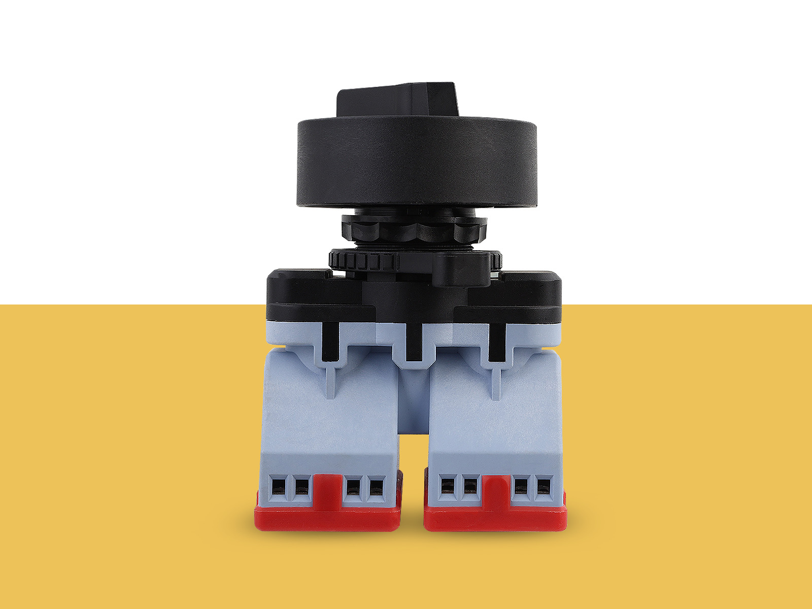
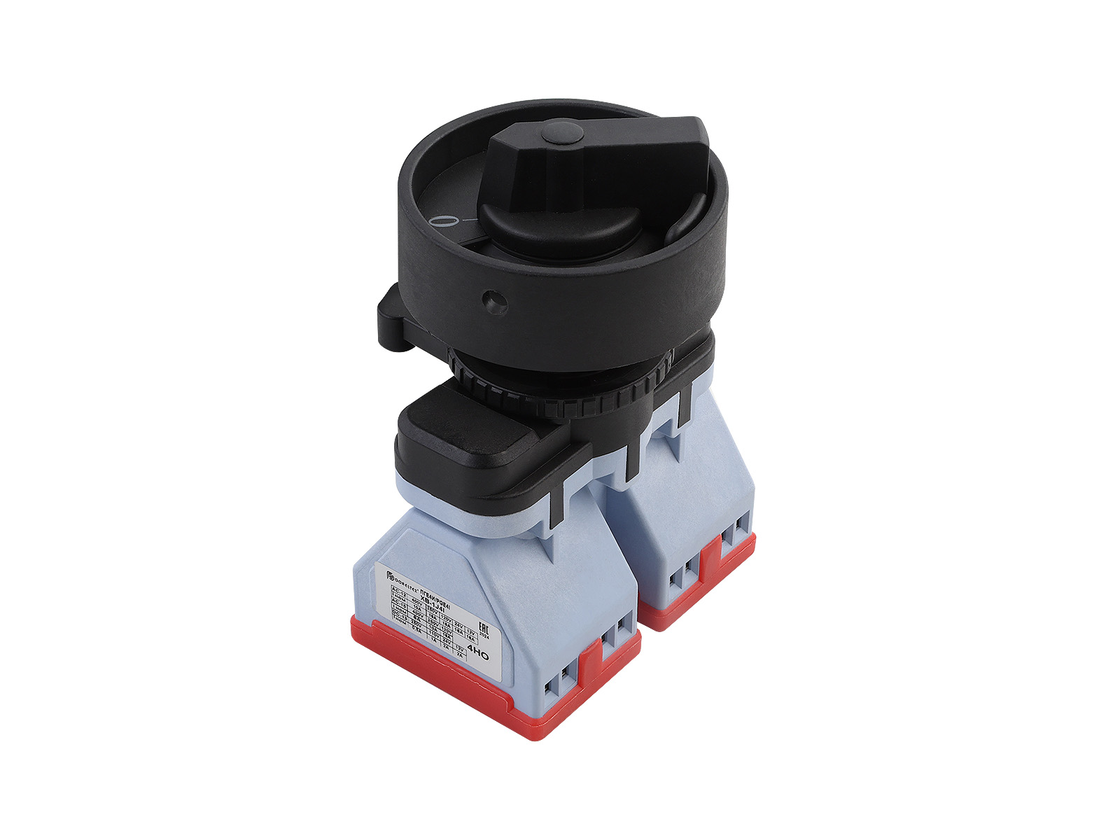
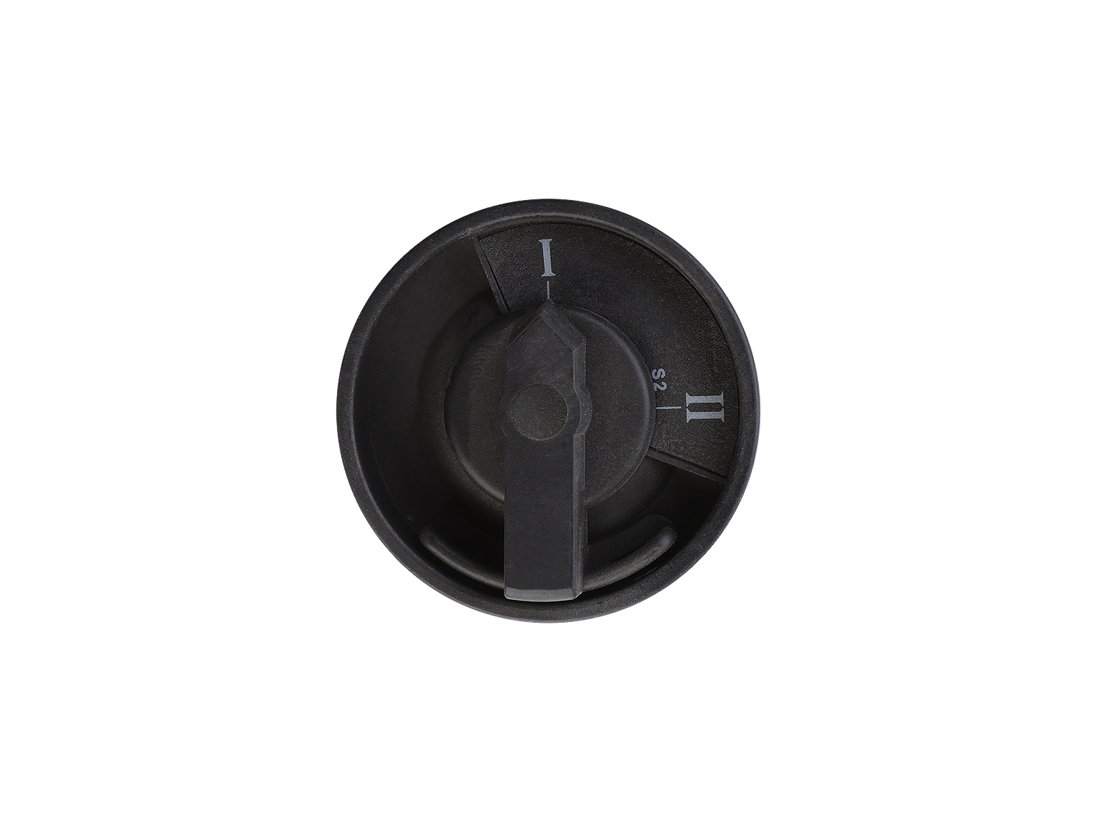
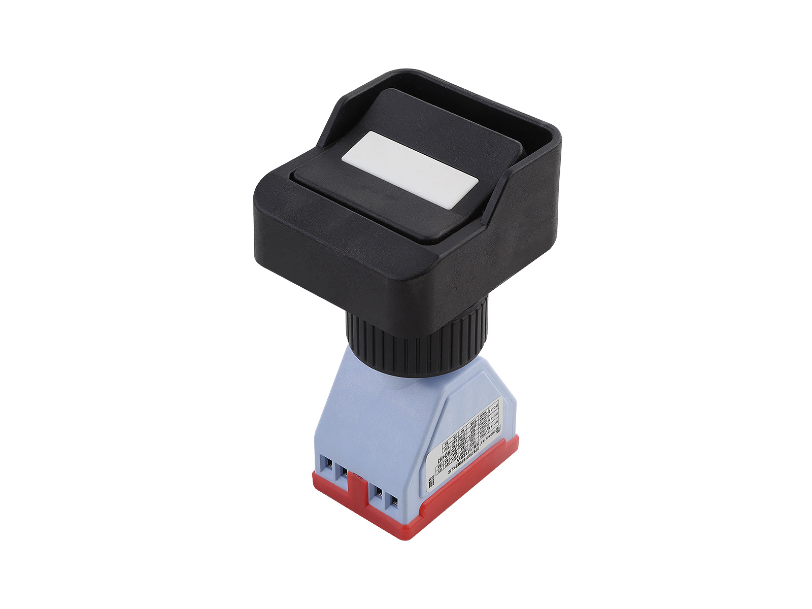
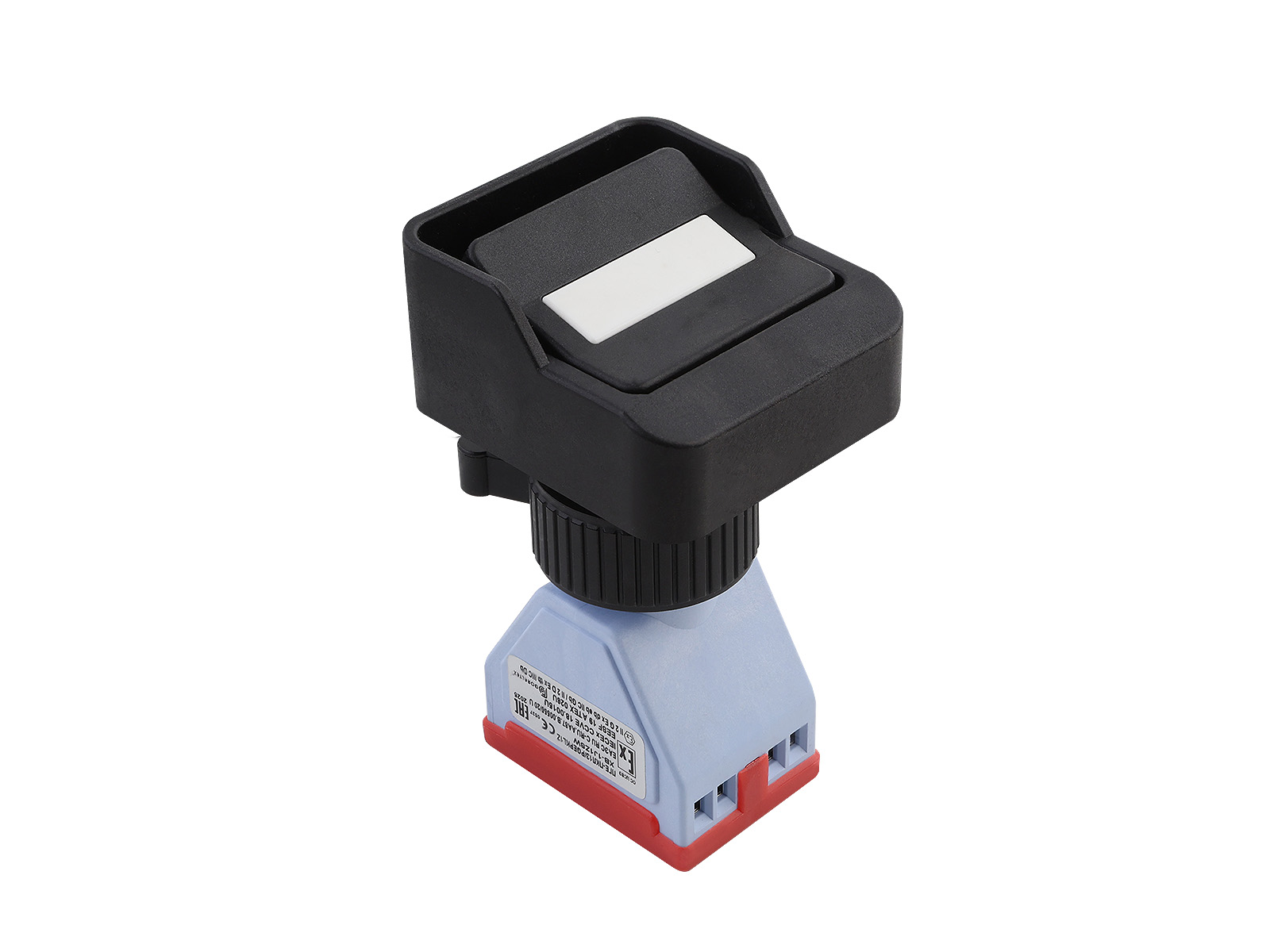
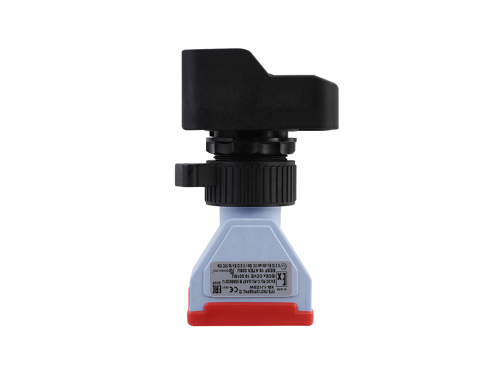
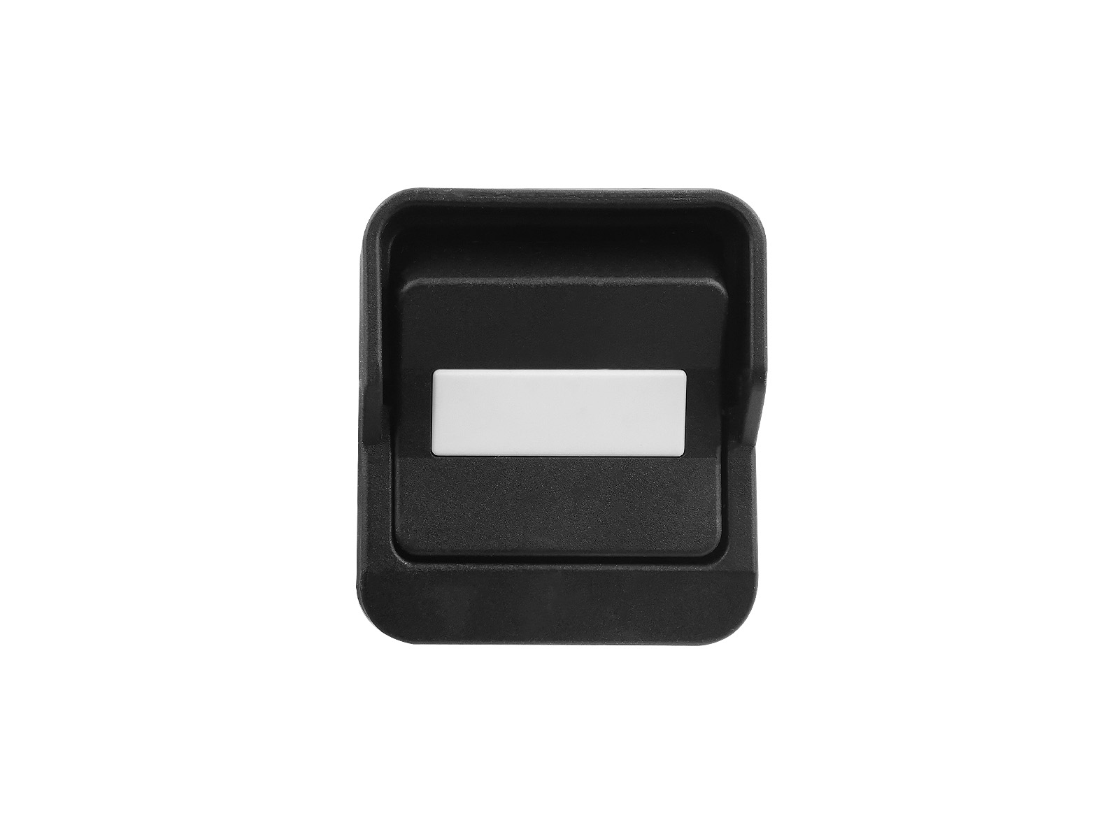
PGE Explosion-Proof Switches

Product Description

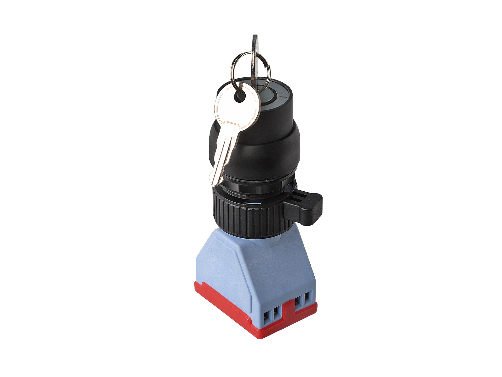
The PGE series switches are designed to control, turn on and off electrical circuits and mechanisms in explosion-proof enclosures with Ex e protection type.

Advantages

  • Certified equipment ensuring safety and uninterrupted operation.
  • Ergonomic design.
  • Possibility of manufacturing buttons with gold-plated contacts used in the design of low-current system circuits - option /CT
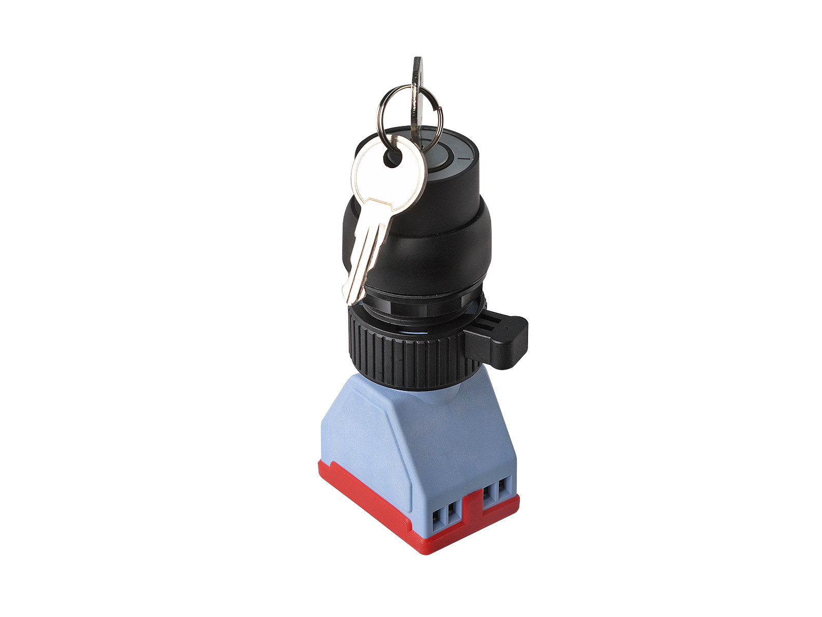
  • Possibility of switching by key or key switch.
  • Possibility of equipping with a cable of any length according to customer requirements.
  • Protection against mechanical damage IK10 and a high degree of protection against moisture and dust IP66/IP67.

Frequently bought together

Markings

Explosion protection marking
Ex db eb IIC Gb U
Ex tb IIIC Db U
Ex db eb I Mc U
Ex ia IIC Ga U
Ex ia IIIC Da U
1Ex db eb IIC T6...T5 Gb X (for PGE...K)
0Ex ia IIC T6...T5 Gb X (for PGE...K)
Ex tb IIIC T85°C...100°C Db X (for PGE...K)
Ex ia IIIC T85°C...100°C Da X (for PGE...K)
Marking of mining equipment
Ex ia I Ma U
RP Ex db eb I Mc X (for PGE...K)
PO Ex ia I Ma X (for PGE...K)
Degree of protection
IP66/IP67
IK10

Technical data

Ambient temperature, °C
-60…+85
-60…+85 (T5/T100°C) (for PGE...K)
-60…+60 (T6/T185°C) (for PGE...K)
Maximum voltage, V
~125
~250
~400
⎓12
⎓24
⎓125
⎓250
~240 (for PGE4I)
~415 (for PGE4I)
Nominal working current, A
AC-3: 16 (at ~400V)
AC-23: 16 (at ~400V)
AC-12: 16 (at ~400V)
AC-15: 10 (at ~400V, ~250V, ~120V, at ~24V, at ~12V),
DC-13: 1 (at ⎓250V), 2 (at ⎓125V), 10 (at ⎓24V), 10 (at ⎓12V)

For PGE4I:
AC-3: 32 (at ~400V, ~250V)
AC-21: 22 (at ~400V, ~250V)
Contact group
1NO+1NC
2NO
4NO
2NO+2NC
Enclosure material
Polyamide
Weight, kg
0,14
Climatic category
NF1 (on demand U1, U2, U3, U4, U5, NF2, NF3, NF4, NF5, HL1, HL2, HL3, HL5, T1, T2, T3, T5, MU1, MU2, MU3, MU4, OM5)

Design parameters

Type Appearance Drawing
PGE1S
PGE2I
PGE1Z
PGE1V
PGE1R
Switches PGE1S, PGE2I, PGE1Z Switches PGE1S, PGE2I, PGE1Z
PGEZ... PGEZ switches PGEZ switches
PGE2S
PGE4I
PGE2Z
PGE2B
Switches PGE2S, PGE4I, PGE2Z
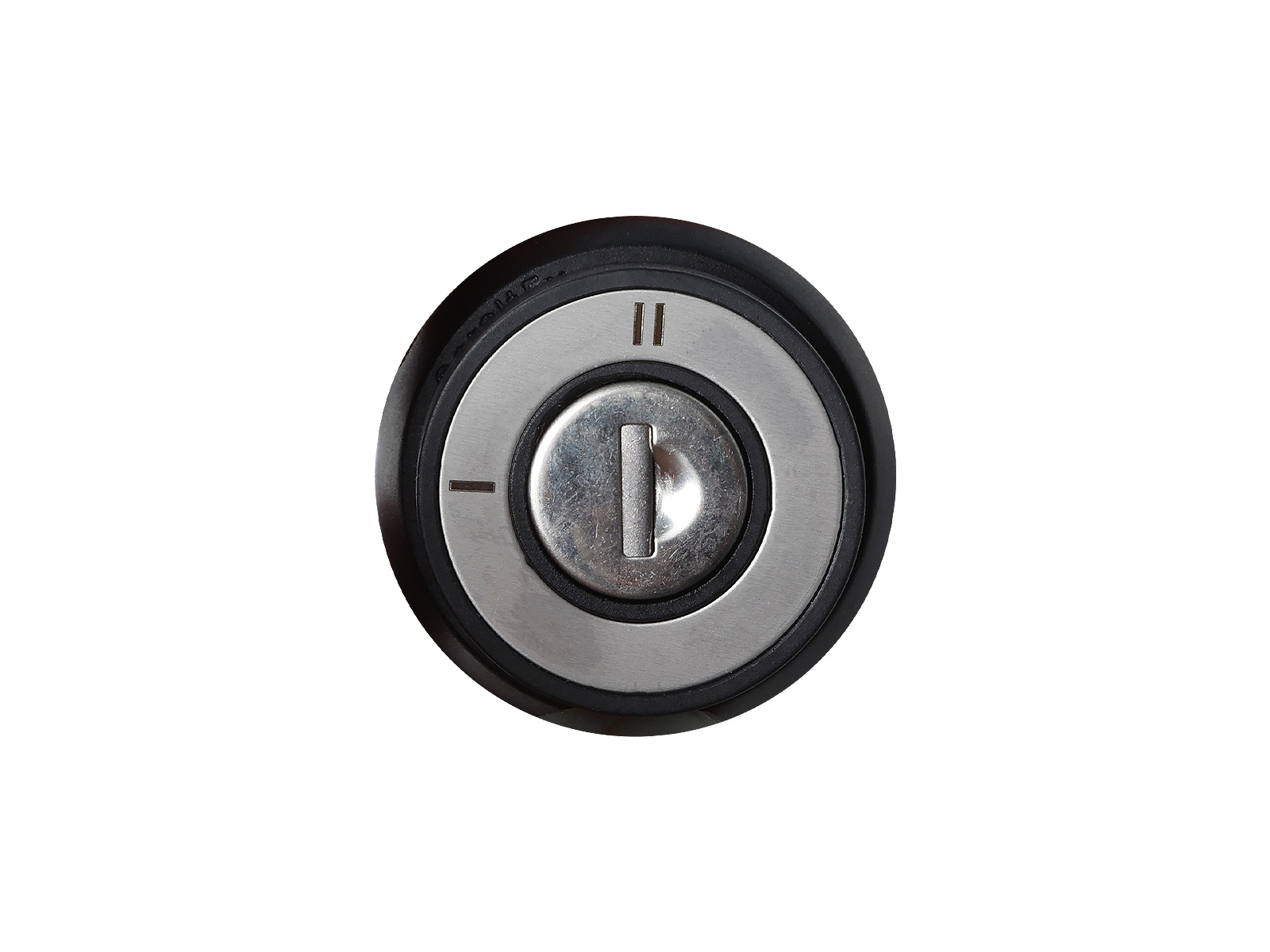
PGEPKL Key switch PGEPKL Key switch PGEPKL
PGE...K PGE...K switches PGE...K switches
PGEZ...K Switches PGÈZ...K Switches PGÈZ...K

Options

Options, accessories and versions
Marking
A locking device for a control element in the form of a lock
/CASTLE1
Reduced size of the switch handle
/TO
Non-explosion-proof design
/PROM
Low-current contact group
/ST
Tropical version with insect protection
/TERMITY
Type Appearance Drawing
/LOCK1
(only for PGEZ..., PGEZ...K)
/CASTLE1 /CASTLE1

Instructions

Control and indicating elements operating manual (LGSA.670305.113RE)
View

Additional information

Type Contacts Description
PGE1S 2NO 3-position switch
with zero, diagram 1C
PGE2I 2NO Switch 2 positions,
circuit 2I
PGE1Z 1 NO + 1 NC Switch 2 positions,
circuit 1Z
PGE1V 2NO 3-position switch, 1W circuit
PREV1R 2NO 3-position switch, 1R circuit
PGEZ1S 2NO Key switch, 3 positions.
The key can be removed in any position. Diagram 1C
PGEZ2I 2NO Key switch, 2 positions.
The key can be removed in any position. 2I diagram
ПГЕЗ1З 1 NO + 1 NC Key switch, 2 positions.
The key can be removed in any position. 1Z diagram.
PGEZ1V 2NO A key-operated switch with 3 positions.
The key is removed in the middle position of the switch. 1W circuit
PGE2S 4NO 3-position switch
with zero circuit 2C
PGE4I 4NO Switch 2 positions
diagram 4I
PGE2Z 2 NO + 2 NC Switch 2 positions
diagram 2Z
PGE2B 2NO 3-position switch,
2W circuit
PGEPKL2I 2NO Switch, 2 positions, circuit 2I
ПГЕПКЛ1З 1 NO + 1 NC Switch, 2 , circuit 1Z
ПГЕПКЛ4И 4NO Switch, 2 positions, circuit 4I
PGE1SK 2NO 3-position switch
with zero, diagram 1C
PGE2IK 2NO Switch 2 positions,
circuit 2I
PGE1ZK 1 NO + 1 NC Switch 2 positions,
circuit 1Z
PGE1VK 2NO 3-position switch,
1W circuit
PGEZ1SK 2NO Key switch, 3 positions.
The key can be removed in any position. Diagram 1C
PGEZ2IK 2NO Key switch, 2 positions.
The key can be removed in any position. 2I diagram
ПГЕЗ1ЗК 1 NO + 1 NC Key switch, 2 positions.
The key can be removed in any position. 1Z diagram.
PGEZ1VK 2NO A key-operated switch with 3 positions.
The key is removed in the middle position of the switch. 1W circuit

Submit request

Quantity
Additional description
0 / 300

Drag files here

CAD " GORELTEX ", questionnaires, necessary documents

Remaining: 20.00 MB
or
Model Breakdown
PGE 1X 2X 3X / 4X
1X - Switch type: no designation - handle, Z - key, PKL - key switch
2X - Circuit diagram: 1C, 2I, 1Z, 1B, 2C, 4I, 2Z, 1P
3X - Connection type: no designation - contact group only, K - device with permanently connected cable
4X - Options, accessories, versions

Example: PGE1ZK/ST

Where to buy GORELTEX products

Saint Petersburg

Head office and production site

Telephone
Address
193149, Leningrad region, Vsevolozhsk district, Novosaratovka village, Rabochaya street, house 9, building 1

Read more

Moscow

Sales office

Telephone
Address
123112, Moscow, Presnenskaya Embankment, 6, building 2, business complex "Imperia Tower", floor 12, office No. 15
Read more

Kazan

Sales office

Telephone
Address
420061, Russia, Republic of Tatarstan, Kazan, st. Nikolay Ershova, 1A, Korston Business Center, floor 11, office No. 1110
Read more

Tyumen

Sales office and production site

Telephone
Address
625031, Russia, Tyumen, Shcherbakova St., 160G
Read more