• Distribution and Terminal Boxes
  • Control and Automation Cabinets
  • Lighting Equipment
  • Control and Indicating Stations
  • Visual, Audible and Signaling Devices
  • Electrical Heating and Fans
  • Video Surveillance
  • IT equipment
  • Spark protection barriers and functional safety relays
  • Cable Glands, Conduits
  • Sockets, Plugs, Extension cords
  • Switches, Selectors Switches, Sensors
  • Control and Measuring Instruments
  • Cable/Pipe Transits
  • Electrical Components and Materials
Logo

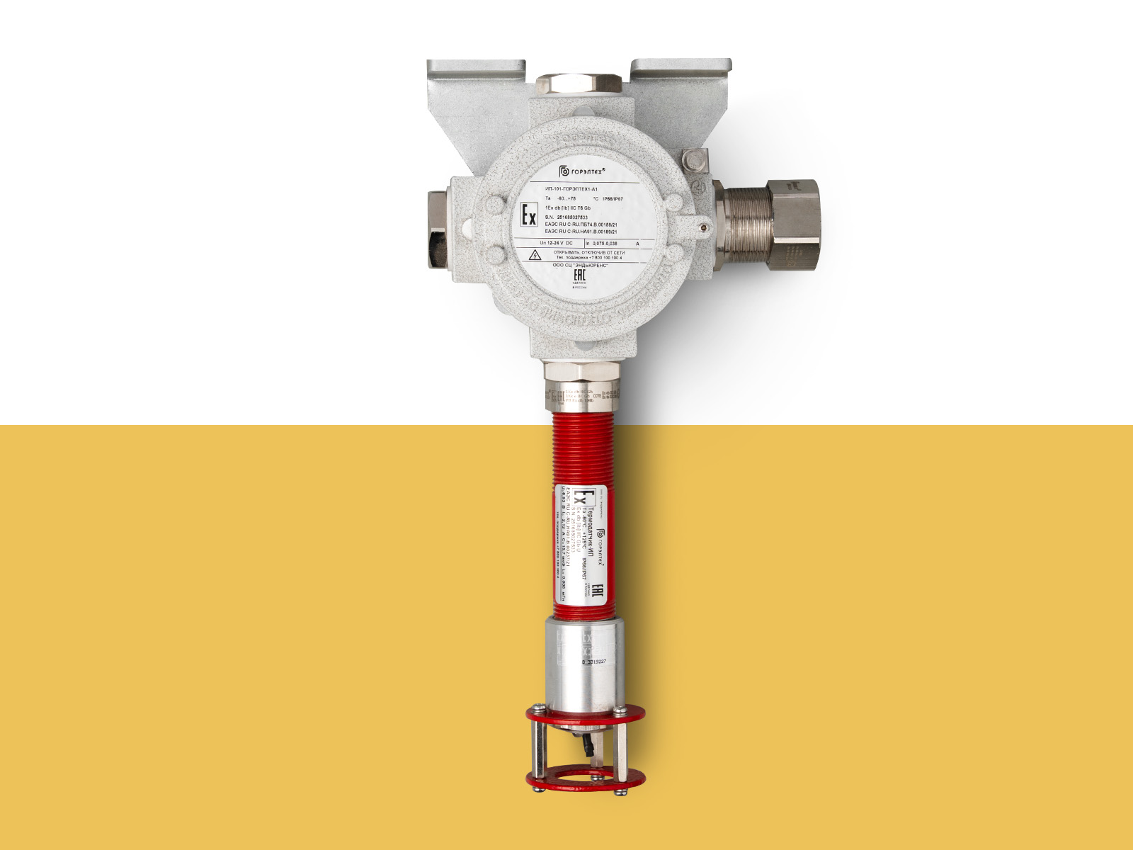
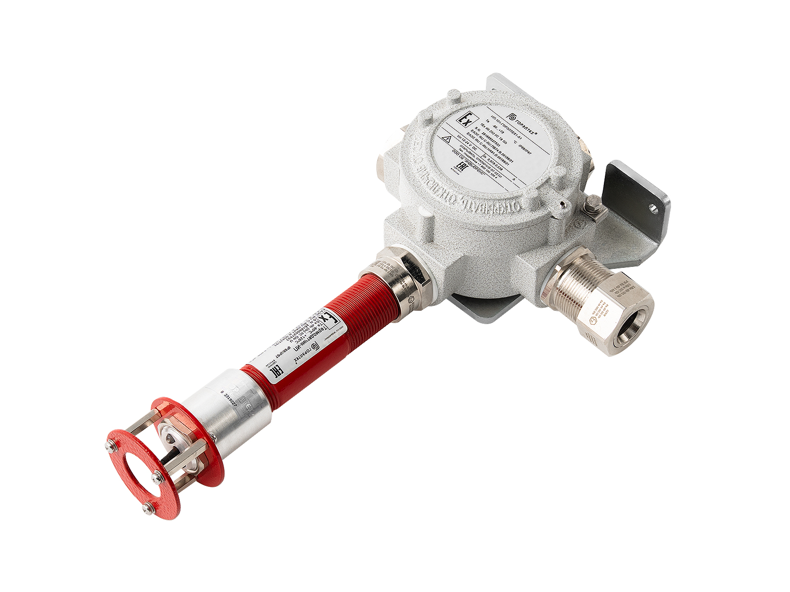
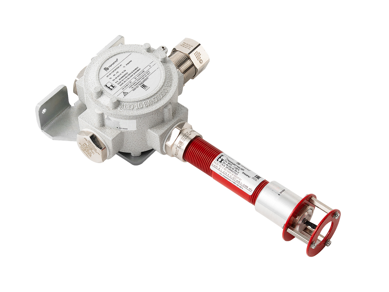
Explosion-proof thermal fire detectors IP-101- GORELTEX 1

Product Description

The IP-101- GORELTEX 1 series of explosion-proof thermal fire detectors are designed to monitor the ambient temperature at various process equipment installations (pumping stations of main oil and gas pipelines, tank farms, loading racks, etc.). When the ambient temperature exceeds the permissible limit, the detectors generate an alarm. They can also be integrated into fire alarm and fire suppression systems.
Explosion-proof thermal fire detectors of the IP-101- GORELTEX 1 series are divided into types A1, A2, A3, B, C, D depending on the fire class in accordance with GOST R 53325-2012.

Advantages

  • The detector's functionality is monitored using a microcontroller installed inside the device, enabling self-diagnostics. The microcontroller automatically polls the temperature sensor and, upon receiving a response, generates a serviceability signal.
  • Data exchange between the temperature sensor and the microcontroller is carried out via a digital protocol. The authenticity of the received data is verified using a checksum mechanism. The likelihood of receiving false data from the temperature sensor and, consequently, false alarm activation is minimized.
  • The presence of dry contacts in the sensor's serviceability relay and the temperature overshoot relay allows the detector to be equipped with addressable tags from third-party manufacturers and integrated with fire alarm systems that support interaction, particularly via proprietary digital protocols. This capability significantly expands the range of applications for the IP-101 detector.
  • Possibility of serial and parallel connection of the detector.
  • For visual monitoring of the fire alarm's status, in addition to a pair of changeover relays, two LEDs are provided (green for detector operation, red for excess temperature). This indicator allows for quick identification of the source of the fault when using multiple detectors in an alarm loop.
  • There are two modifications of detectors: powered by a 12-24 V DC source and by a 230 V 50 Hz AC source.

Frequently bought together

Compliance with standards

GOST 12.2.007.0-75
GOST R IEC 60079-0-2011
GOST 14254-96 (IEC 529-89)
GOST 30852.0-2002 (IEC 60079-0:1998)
GOST 30852.1-2002 (IEC 60079-1:1998)
GOST 30852.10-2002 (IEC 60079-11:1999)
GOST 30852.8-2002 (IEC 60079-0:1998)
GOST 30852.20-2002
GOST 24754-2013
TR CU 012/2011
Chapter 7.3 of the Electrical Installation Code
Chapter 7.4 of the Electrical Installation Code
GOST R 53325-2009

Certificates

Markings

Explosion protection marking
1Ex db ib IIC T6…T4 Gb
Marking of mining equipment
RN1/RN2
Degree of protection
IP66/IP67
IK08
Installation
Category I for firedamp and dust;
Category II for gas subgroups IIA, IIB, IIC, zones 1, 2;
Underground workings that are not hazardous for gas (methane) and coal dust

Technical data

Ambient temperature, °C
for A1/A2: -60…+75 (T6/85°C)
for A3/B: -60…+90 (T5/100°C)
for C/D: -60…+125 (T4/135°C)
Response temperature, °C
for A1: min 54, max 65
for A2: min 54, max 70
for A3: min 64, max 76
for B: min 69, max 85
for C: min 84, max 100
for D: min 99, max 115
Operating voltage, V
~90...230 (50/60 Hz); ⎓6…24;
Maximum switching voltage of relay contacts, V
~230 (50/60 Hz)
Maximum current consumption, A
no more than 1
Maximum switching current of relay contacts, A
5 (for ~220 V (50/60 Hz))
Installed power (at operation) Py, W
0.9 (⎓12 V)
1.76 (~220 V (50/60 Hz))
Connection
Connection to terminals L, N, PE and signal terminals of the detector, cable cross-section up to 2.5 mm2
Threads on connecting holes
Metric M25x1.5 GOST 24705-2004
Coating
Antistatic polymer-epoxy coating, friction-proof, spark-proof, resistant to working environments and ionizing radiation. Color RAL 3001
Enclosure material
Aluminum alloy with alloying modifiers
Detector class according to GOST R 53325-2012
A1, A2, A3, B, C, D
Protection class against electric shock
I
Weight, kg
no more than 3 (depending on the configuration)
Climatic category
NF1 (as required NF2, NF3, NF4, NF5, HL1, HL2, HL3, HL5, T1, T2, T3, T5, MU1, MU2, MU3, MU4, W2.1 , W5 )

Design parameters

Explosion-proof digital thermal point fire alarm IP-101-A1- GORELTEX

Options

Options, accessories and versions
Marking
Anti-condensation coating
/AP
Protective visor
/KOZYREK
Non-explosion-proof design
/PROM
Mining normal design
/RN

3D models

STP models
zip
Download

Additional information


Rate of temperature increase
, °C/min
Response time, s
minimum maximum
for fire class
A1
for fire class
A2, A3, B, C, D
1 1740 2420 2760
3 580 820 960
5 348 500 600
10 174 260 329
20 87 140 192
30 58 100 144

Layout of interface board contacts (for /12DC modification)

Layout of interface board contacts (for /12DC modification)

Interface board terminal block pin assignment for 12V DC modification
Contact designation Purpose
-ShS Alarm loop (minus)
Sensor serviceability relay K1 NC1 Normally closed contact of the sensor serviceability relay. Open (closed) if the sensor is serviceable (failure)
CMU1 Common contact of the sensor serviceability relay
+V +12…24 V DC
0 0
PE Grounding
Thermostat relay K2 NC2 Normally closed contact of the thermostat relay. Closed if the temperature has not exceeded T max
CMU2 Common contact of thermostat relay
NO2 Normally open contact of the thermostat relay.
Closed if the temperature has exceeded T max and has not dropped below T min.


Interface board pinout for 220V AC modification

Interface board pinout for 220V AC modification

Assignment of contacts of the interface board terminals for the 220 V AC modification
Contact designation Purpose
-ShS Alarm loop (minus)
Sensor serviceability relay K1 NC1 Normally closed contact of the sensor serviceability relay. Open (closed) if the sensor is serviceable (failure)
CMU1 Common contact of the sensor serviceability relay
L Phase 220 V 50 Hz AC
N Neutral 220 V 50 Hz AC
PE Grounding
Thermostat relay K2 NC2 Normally closed contact of the thermostat relay. Closed if the temperature has not exceeded T max
CMU2 Common contact of thermostat relay
NO2 Normally open contact of the thermostat relay.
Closed if the temperature has exceeded T max and has not dropped below T min.


Connection diagrams for the IP-101-GORELTEX1 detector to the fire alarm control panel
(FIRE CONTROL AND RECEPTION SYSTEM)

Connection diagrams for the IP-101- GORELTEX 1 detector to the fire alarm control panel

Connection diagrams for the IP-101- GORELTEX 1 detector to the fire alarm control panel

The components shown in the diagram are housed in the explosion-proof detector box. The ratings are selected based on the type of fire alarm control panel being used. The component ratings for the most common types of fire alarm control panels are summarized in the table:

Assignment of contacts of the interface board terminals for the 220 V AC modification
Type of control panel Connection parameters
Parallel connection (for short circuit) Sequential connection (on opening)
LB-07

Rд must provide current consumption >15 mA,
Rок = 2 kOhm,
VDок = KD522.

Rd = 11 kOhm,
Rok = 2 kOhm,
VDok = KD522.

Beam

Rd = 2.4 kOhm,
Rok = 2.4 kOhm,
VDok = KD521A.

Rd = 2.2 kOhm,
Rok = 2.4 kOhm,
VDok = KD521A.

PPK-2

Rd = 1.2 kOhm,
Rok = 3.6 kOhm,
VDok = KD521A.

Rd = 10.0 kOhm,
Rok = 3.6 kOhm,
VDok = KD521A.

Bolide Rд = 1.5 kOhm (3.0 kOhm - to determine double operation),
Rок = 4.7 kOhm, instead of VDок - jumper

Rд = 8.2 kOhm (4.7 kOhm - to determine double operation),
Rок = 4.7 kOhm, instead of VDок - jumper

Yakhont-16i

Rд = 1.8 kOhm (4.0 kOhm - to determine double operation),
Rок = 8.2 kOhm, instead of VDок - jumper

Not applicable
VERS

Rд = 820 Ohm (1.8 kOhm - to determine double operation),
Rок = 7.5 kOhm, instead of VDок - jumper

Rд = 10 kOhm (4.7 kOhm - to determine double operation),
Rок = 7.5 kOhm. Instead of VDок - jumper

Submit request

Configurator
Fire class designation:
Quantity
Additional description
0 / 300

Drag files here

CAD " GORELTEX ", questionnaires, necessary documents

Remaining: 20.00 MB
or
Model Breakdown
IP-101-GORELTEX1 - 1X - 2X - 3X / 4X – TU 26.30.50-050-72453807-2017
1X - Fire class designation according to GOST R 53325-2012: A1, A2, A3, B, C, D
2X - Operating voltage: ⎓6…24 V - 12DC; ~90...250 V - 220AC
3X - Number and size of cable entry
4X - Options, accessories and versions

Example: IP-101- GORELTEX 1-A1-220AC-KNV1N-TU 26.30.50-050-72453807-2017

Where to buy GORELTEX products

Saint Petersburg

Head office and production site

Telephone
Address
193149, Leningrad region, Vsevolozhsk district, Novosaratovka village, Rabochaya street, house 9, building 1

Read more

Moscow

Sales office

Telephone
Address
123112, Moscow, Presnenskaya Embankment, 6, building 2, business complex "Imperia Tower", floor 12, office No. 15
Read more

Kazan

Sales office

Telephone
Address
420061, Russia, Republic of Tatarstan, Kazan, st. Nikolay Ershova, 1A, Korston Business Center, floor 11, office No. 1110
Read more

Tyumen

Sales office and production site

Telephone
Address
625031, Russia, Tyumen, Shcherbakova St., 160G
Read more