


 EAEU RU C-RU.AB29.B.02260/24
 EAEU RU D-RU.PA02.B.52415/24
 ROSS RU.FB01.N00085/24
Saint Petersburg
Head office and production site
Telephone
Address
193149, Leningrad region, Vsevolozhsk district, Novosaratovka village, Rabochaya street, house 9, building 1

 Log in to your account
 [Ex ia Ga] IIC [Ex ia Ga] IIB [Ex ia Ga] IIA [Ex ia Ma] I [Ex ia Da] IIIС
| Main parameters | |||
| Response time | ≤ 20 ms | ||
| Power consumption | ≤ 1 W | ||
| Dielectric strength |
alternating current (intrinsically safe and non-intrinsically safe sides) | ≥ 2500 V | |
| AC (power/non-intrinsically safe side) | ≥ 500 V | ||
| Insulation resistance (input/output/power supply) |
≥ 100 MOhm | ||
| Operating temperature | -20°C… +60°C | ||
| Storage temperature | -40 °C… +80 °C | ||
| Dimensions | width | 15.8 mm | |
| height | 121.6 mm | ||
| depth | 104.8 mm | ||
| Transfer parameters | |||
| The main error | 0.1% (the normalizing value for the given error is the input signal range) | ||
| Limits of permissible additional error due to changes in air temperature |
0.005%/ºС (the normalizing value for the given error is the input signal range) | ||
| Maximum safe voltage | 250 V | ||
| Intrinsic safety parameters | terminals 1, 2; 4, 5 | ||
| II C : | II B, IIIC: | II A, I : | |
| U0, B | 10,5 | 10,5 | 10,5 |
| I0, mA | 11,3 | 11,3 | 11,3 |
| P0, mW | 29,7 | 29,7 | 29,7 |
| C0, μF | 0,97 | 0,97 | 52 |
| L0, mH | 100 | 300 | 300 |
| Nutrition | |||
| Power supply | =18-32 Reverse polarity protection | ||
| Input parameters | |||
| Input signal | Dry contact or NAMUR | ||
| Output parameters | |||
| Output signal | Relay contact | ||
| Response parameters | |||
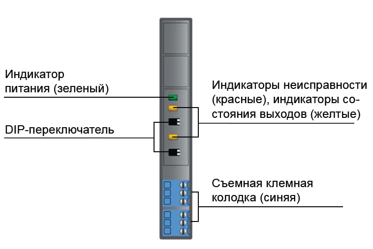
| In. signal > 2.1 mA signal “1” | the yellow LED is on | ||
| In. signal < 1.2 mA signal “0” | the yellow LED does not light | ||
| Open circuit voltage | ~8.2 V | ||
| Short-circuit current | 8 mA | ||
| Switching capacity | 35VDC/0.5A | ||
| Mechanical resource | > 100,000 switching cycles | ||
| Switching frequency, Hz | < 10 | ||
| DIP switch settings | |||
| Switch state |
a | b | |
| S | Channel 1 – Direct Mode | Channel 1 – inverse mode | |
| S | Channel 1 Line Fault Detection Function Enabled | Channel 1 Line Fault Detection Function Disabled | |
| S | Channel 2 – Direct Mode | Channel 2 – inverse mode | |
| S | Channel 2 Line Fault Detection Function Enabled | Channel 2 line fault detection function is disabled | |
| Line fault detection function | |||
| If the output load resistance is less than 80 ohms, the device detects this condition as an output short circuit. If the output load resistance exceeds 6000 ohms, the device detects this condition as an open circuit. In the event of a fault, the input current is limited to 1 mA, and the output current is limited to 3 mA. |
|||


Drag files here
CAD " GORELTEX ", questionnaires, necessary documents
Head office and production site
Sales office
Sales office
Sales office and production site
Sales office
Sales office

