


 EAEU RU C-RU.AZh58.V.04078-23
 EAEU N RU D-RU.RA05.V.77977-23
 ROSS RU.FB01.N00061_23

Saint Petersburg
Head office and production site
193149, Russia, Leningrad region, Vsevolozhsk district, Novosaratovka village, Rabochaya street, house 9, building 1

 Log in to your account
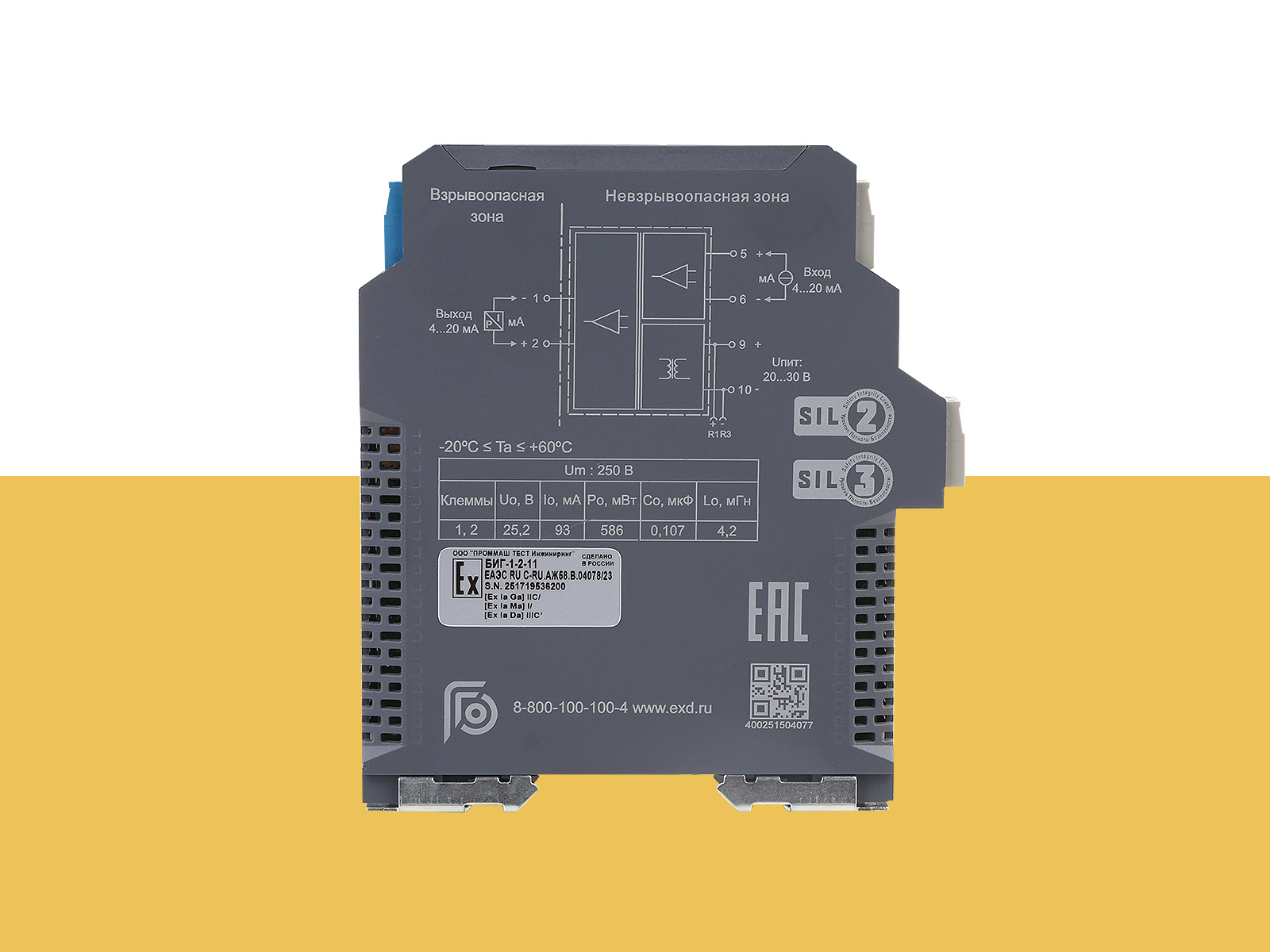
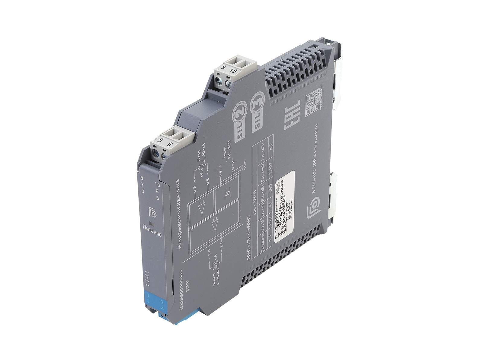
 [Ex ia Ga] IIC [Ex ia Ga] IIB [Ex ia Ga] IIA [Ex ia Ma] I [Ex ia Da] IIIС
| Main parameters: | |||||
| Safety Integrity Level (SIL): | SIL 2 | ||||
| Operating temperature, °C: | -20 … +60 | ||||
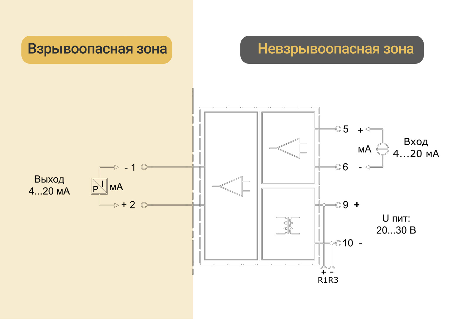
| Power supply, V: | = 20..30. Reverse polarity protection | ||||
| Input signal, mA: | 4…20, HART | ||||
| Output signal, mA: | 4…20, HART | ||||
| Input voltage drop, V: | ≤ 1,2 | ||||
| Load RL , Ohm: | 80…800 | ||||
| DIN rail mounting, mm: | 35 | ||||
| Maximum safe voltage, V: | 250 | ||||
| Intrinsic safety parameters: | |||||
| terminals 1, 2 | |||||
| II C: | II B: | II A : | |||
| U0 , B: | 25,2 | 25,2 | 25,2 | ||
| I0 , mA | 93 | 93 | 93 | ||
| P0 , mW | 586 | 586 | 586 | ||
| C0 , μF | 0,107 | 0,82 | 2,9 | ||
| L0, mH | 4,2 | 12,6 | 33,6 | ||
| Transfer parameters: | |||||
| Error, %: | 0,1 | ||||
| Effect of temperature: | ≤30 x 10-6 /°C: | ||||
| Response time, ms: | ≤ 2 | ||||
| Power consumption, W: | ≤ 1,0 | ||||
| Galvanic isolation, V: | |||||
| alternating current between intrinsically safe and non-intrinsically safe circuits |
≥ 3000 | ||||
| alternating current between the supply circuit and non-intrinsically safe circuits |
≥ 1500 | ||||
| Insulation resistance (between input/output/power supply), MOhm: | ≥ 100 | ||||
| Output signal value in safe state, mA: | <3.6 or >21.5 | ||||
| Output 2 parameters: | Detection of an output load impedance of less than 80 ohms at the pin is defined as a short circuit. Detection of an output load impedance of greater than 6000 ohms at the pin is defined as an open circuit. In both fault conditions, the input current is limited to 1 mA, and the output current is limited to 3 mA. | ||||


Drag files here
CAD " GORELTEX ", questionnaires, necessary documents
Head office and production site
Sales office
Sales office
Sales office and production site
Sales office
Sales office

