


 EAEU RU C-RU.AZh58.V.04078-23
 EAEU N RU D-RU.RA05.V.77977-23

Saint Petersburg
Head office and production site
Telephone
Address
193149, Leningrad region, Vsevolozhsk district, Novosaratovka village, Rabochaya street, house 9, building 1

 Log in to your account
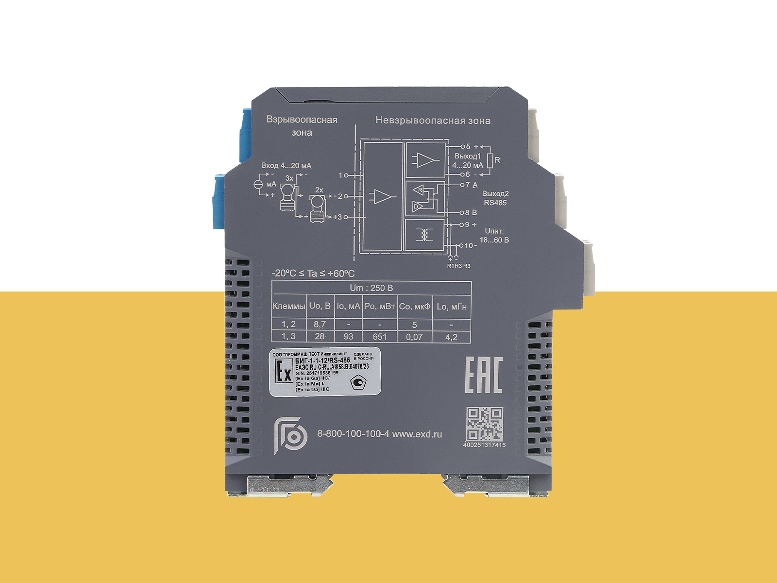
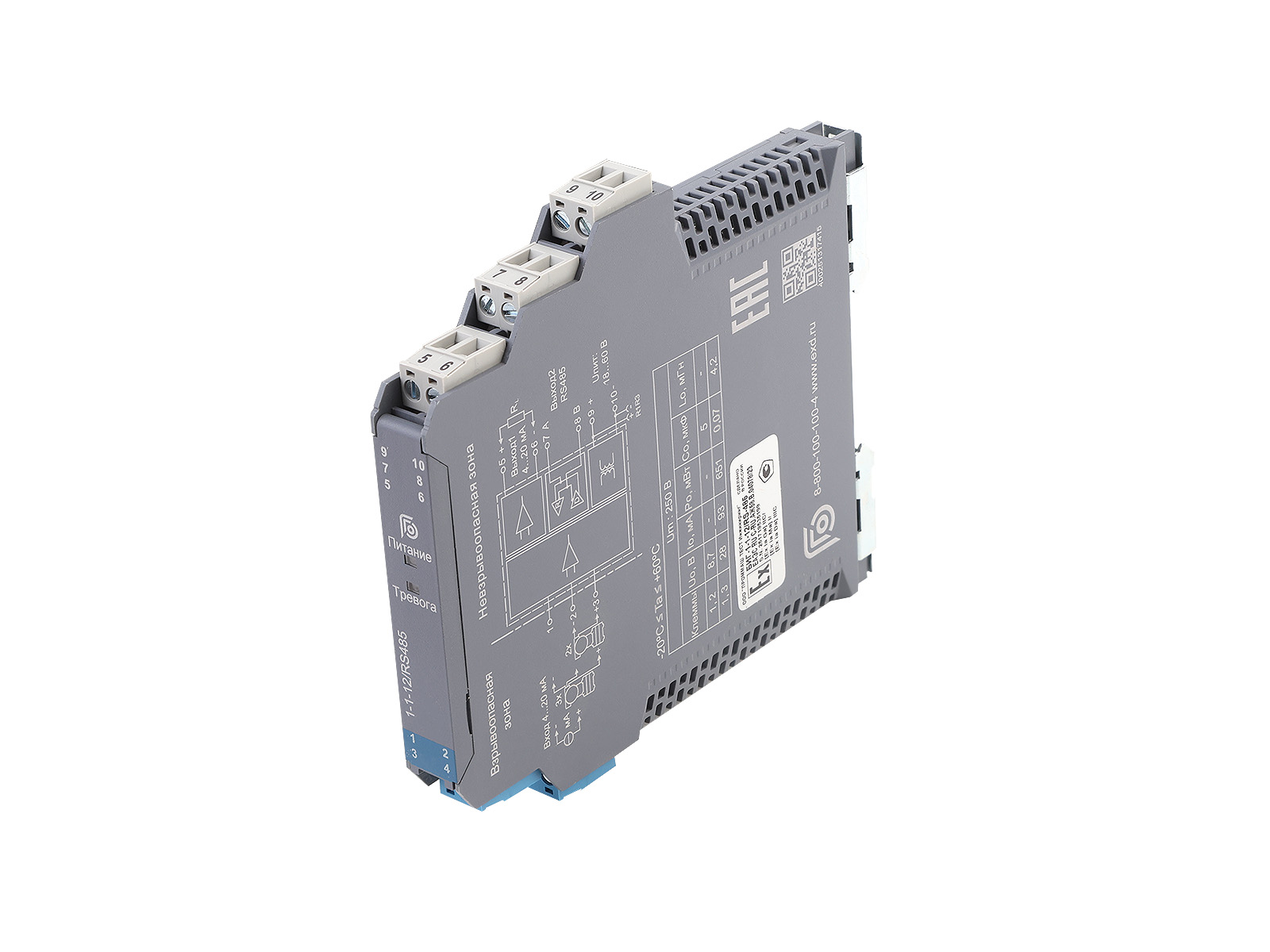
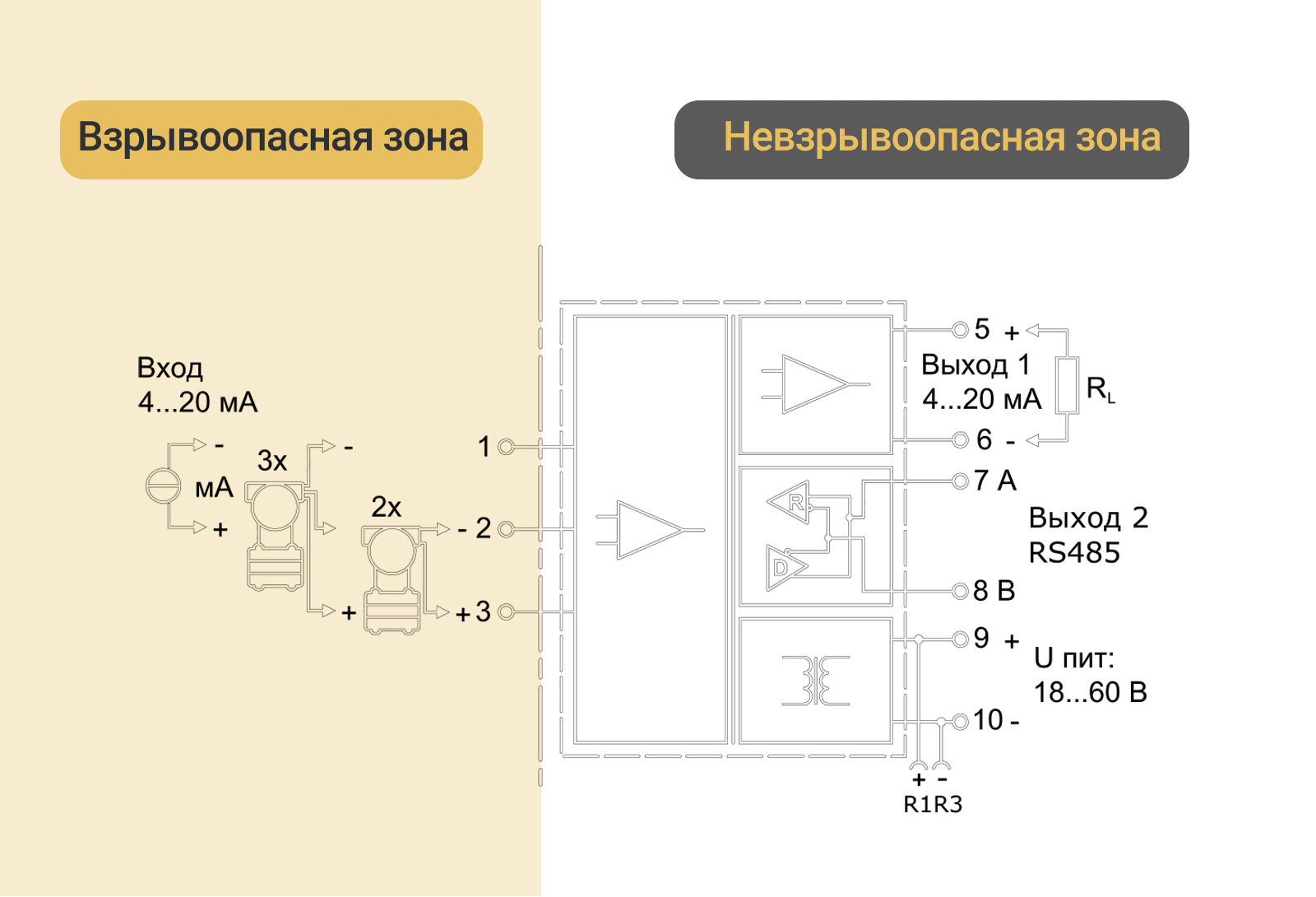
 [Ex ia Ga] IIC [Ex ia Ga] IIB [Ex ia Ga] IIA [Ex ia Ma] I [Ex ia Da] IIIС
| Main parameters: | ||||||
| Inter-verification interval: | 2 years - BIG-1-1-12/RS485* 4 years - BIG-1-1-12/RS485/P* *By default, barriers are supplied without initial verification. Please indicate the need for verification when submitting your request. The verification cost will be specified when issuing the technical quotation. Verification increases the delivery time by approximately two weeks. |
|||||
| Operating temperature, °C: | -20 … +60 | |||||
| Power supply, V: | = 18..60 Reverse polarity protection | |||||
| Input signal, mA: | 4…20 | |||||
| Input impedance, Ohm: | ≤ 100 | |||||
| Open circuit voltage, V: | ≤ 26 | |||||
| Operating voltage, V at 20 mA: | ≥ 16 | |||||
| Output signal output 1, mA: | 4…20 | |||||
| Load RL , Ohm: | ≤ 550 | |||||
| DIN rail mounting, mm: | 35 | |||||
| Maximum safe voltage, V: | 250 | |||||
| Intrinsic safety parameters: | ||||||
| terminals 1, 2 | terminals 1, 3 | |||||
| II C: | II B: | II A: | II C: | II B: | II A: | |
| U0 , B: | 8,7 | 8,7 | 8,7 | 28 | 28 | 28 |
| I0 , mA | 93 | 93 | 93 | |||
| P0 , mW | 651 | 651 | 651 | |||
| C0 , μF | 5 | 35 | 700 | 0,07 | 0,63 | 2,13 |
| L0, mH | 4,2 | 12,6 | 33,6 | |||
| Transfer parameters: | ||||||
| Error, %: | 0,1 | |||||
| Effect of temperature: | ≤30 x 10-6 /°C: | |||||
| Response time, ms: | ≤ 500 | |||||
| Power consumption, W: | ≤ 1,7 | |||||
| Galvanic isolation, V: | ||||||
| alternating current between intrinsically safe and non-intrinsically safe circuits |
≥ 3000 | |||||
| alternating current between the supply circuit and non-intrinsically safe circuits |
≥ 1500 | |||||
| Insulation resistance (between input/output/power supply), MOhm: | ≥ 100 | |||||
| Output signal value in safe state, mA: | <3.6 or >21.5 | |||||
| Output 2 parameters: | ||||||
| Transfer protocol: | MODBUS-RTU | |||||
| Maximum distance, m: | ≤ 1000 | |||||
| Number of nodes: | ≤ 32 | |||||
| Transfer speed, kbps: | ≤ 19,2 | |||||
| Output channel 2 statuses: | Regardless of the input fault condition (except for open or short circuit, the output is 0 V/mA), the output value follows the input value within the measurement range. The maximum value should not exceed 110% of the upper limit of the measurement range (e.g., when the output signal type is 0…20 mA, the minimum output value can be 0 mA, but the maximum output value does not exceed 22 mA) | |||||


Drag files here
CAD " GORELTEX ", questionnaires, necessary documents
Head office and production site
Sales office
Sales office
Sales office and production site
Sales office
Sales office

