


RFBG-131-R-24AC-DC Functional Safety Relay
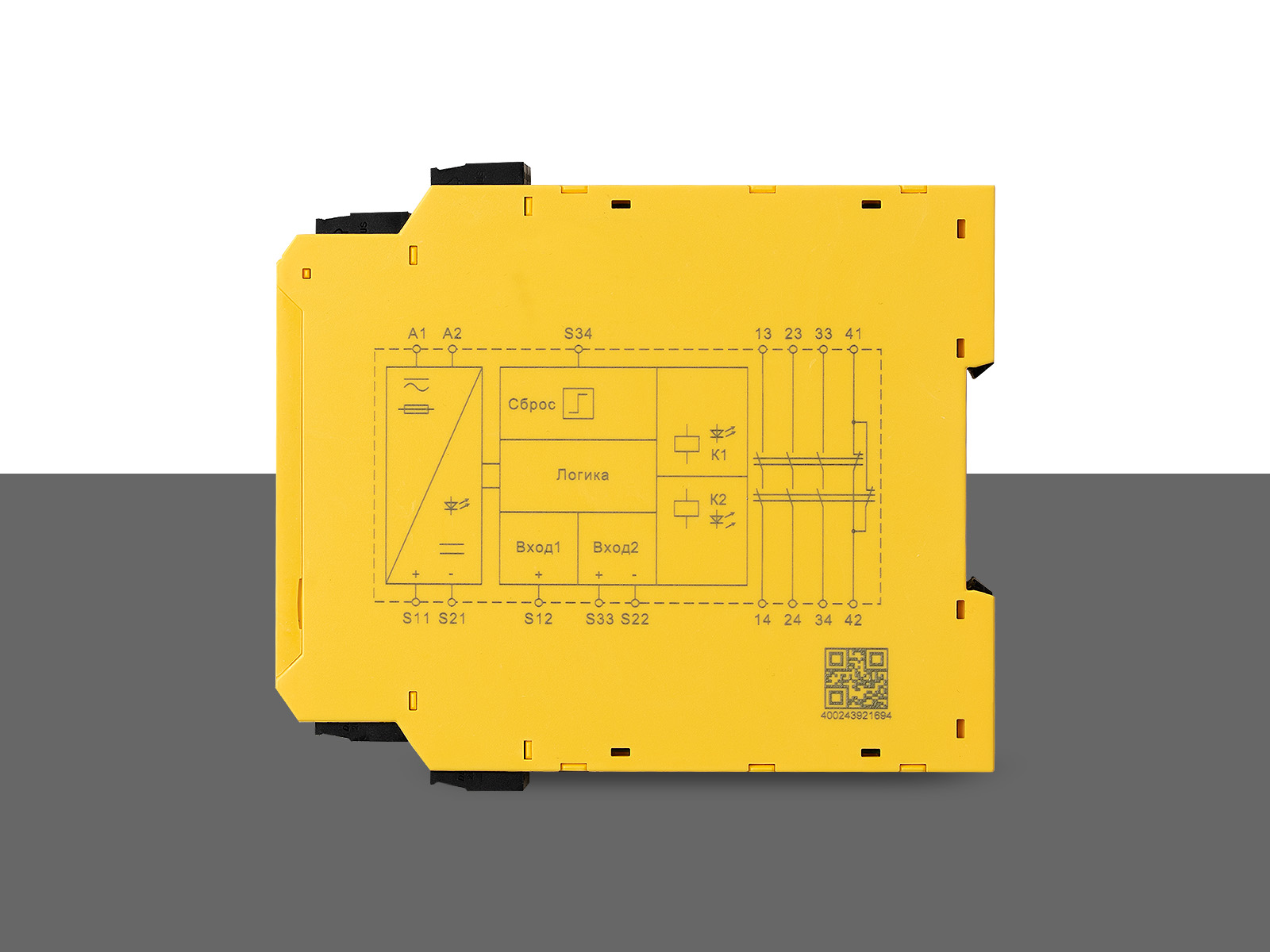
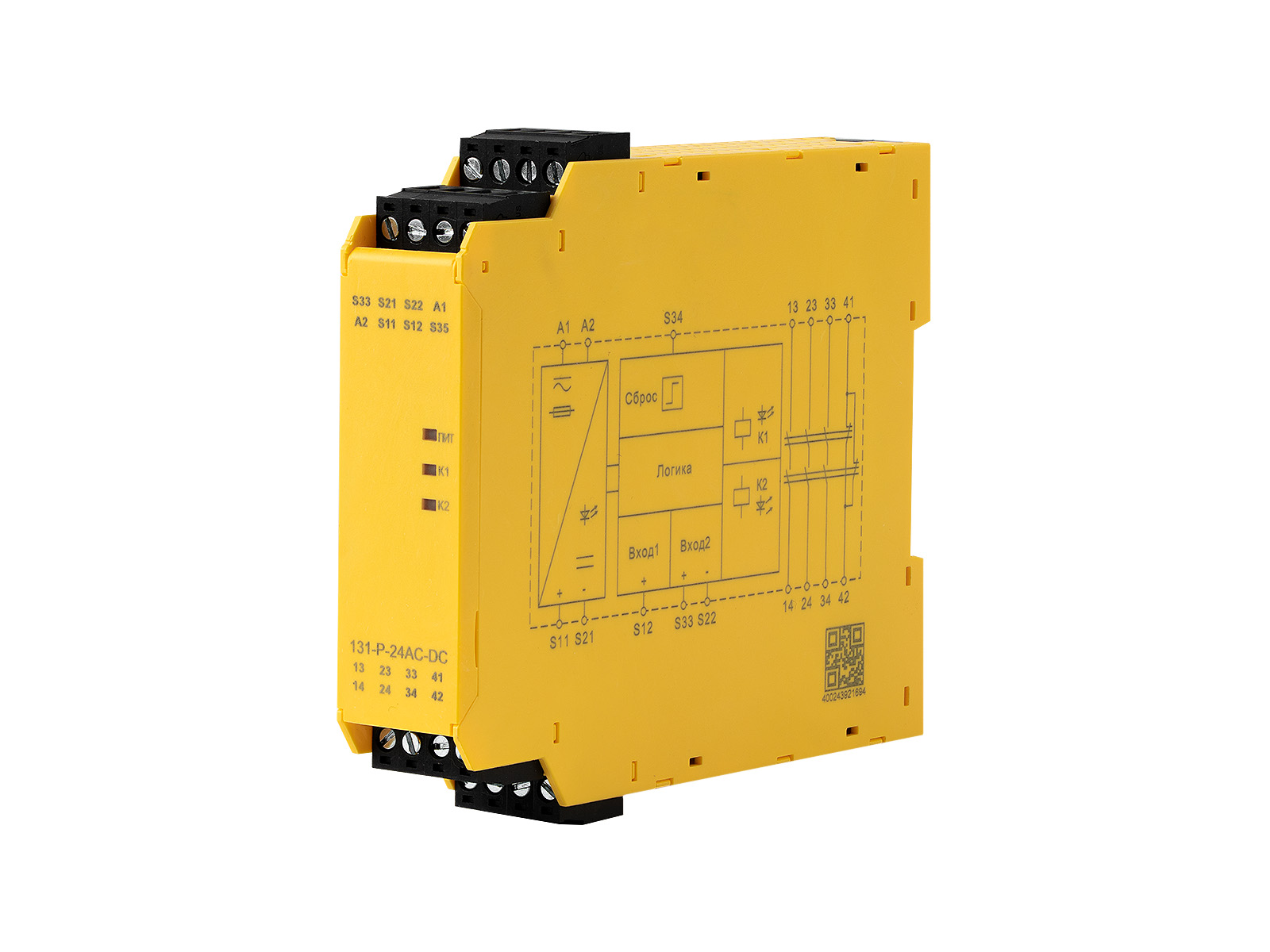


Product Description
Advantages
- 1oo2 architecture.
- Detection of short circuits on contacts.
- Controlled manual reset.
- The safety function remains operational even if components fail.
- Correct operation of the safety relay is tested automatically during each on-off cycle.
| Main parameters | |
| Voltage range, V | ~/=24 |
| Voltage tolerances, V | 0,85… 1,1 |
| Frequency, Hz | Frequency, Hz 50… 60 |
| Heat output, W | ≤ 2.2 at =24 V, ≤ 5.4 at ~24 V |
| Current consumption at =24V, mA | ≤ 50 |
| Cable resistance, Ohm | 15 |
| Input devices | emergency stop button, safety gate |
| Signal type | 3no + 1nz |
| Contact type | forced management |
| Contact material | AgSnO2 + 0.2 μm Au |
| Load characteristics | AC-15: 5 A / 230 V; DC-13: 5 A / 24 V |
| Fuse characteristics | 10 A gL/gG(no), 6 A gL/gG(no) |
| Response time, ms | Auto: ≤ 300, manual: ≤ 150 |
| Opening, ms | Auto stop: ≤ 30, power failure: ≤ 100 |
| Recovery time, ms | Auto stop: ≤ 30, power failure: ≤ 100 |
| Power interruption, ms | 20 |
| Electromagnetic compatibility | IEC/EN 80947, IEC 61326-3-1, IEC/EN 61000-6-2, IEC/EN 61000-6-4 |
| Nominal insulation voltage , V AC |
250 |
| Nominal pulse voltage, V | 6000 (1.2/50 µs) |
| Dielectric strength, V | 1500 (within 1 min) |
| Gaps and leaks | According to IEC 80947-1 |
| Vibration, Hz | 10…55 (0.35 mm) |
| Overvoltage category | III |
| Degree of pollution | 2 |
| Degree of dust and moisture protection | IP20 |
| Operating temperature, °C | -20…. +60 |
| Storage temperature, °C | -40…. +80 |
| Altitude above sea level, m | ≤ 2000 |
| Number of operations, cycles | 10 x 106 |
| Security parameters | |
| Safety Integrity Level (SIL) | 3 |
| Average diagnostic coverage (DC avg), % | 99 |
| Mean time to failure (MTTFD), years | 164 |
| Hardware Fault Tolerance (HFT) | 1 |
| Safe failure rate (SFF), not less than, % | 99 |
| Average probability of dangerous failure on demand (PFDavg/PTI) | 1,29×10⁻⁵ |
| Probability of failure per hour (PFH), 1/h | 1,49×10⁻¹⁰ |
| Stop category | 0 |
| Connection diagram | |
 |
|
Additional information
Possible applications:

Input: "Emergency stop", 2-channel.
With short-circuit signaling on contacts.
Controlled manual reset.
Output: 3 NO + 1 NC (auxiliary).
Submit request
Quantity
Additional description
0 / 300
Drag files here
CAD " GORELTEX ", questionnaires, necessary documents
or

