


Saint Petersburg
Head office and production site
193149, Russia, Leningrad region, Vsevolozhsk district, Novosaratovka village, Rabochaya street, house 9, building 1

 Log in to your account
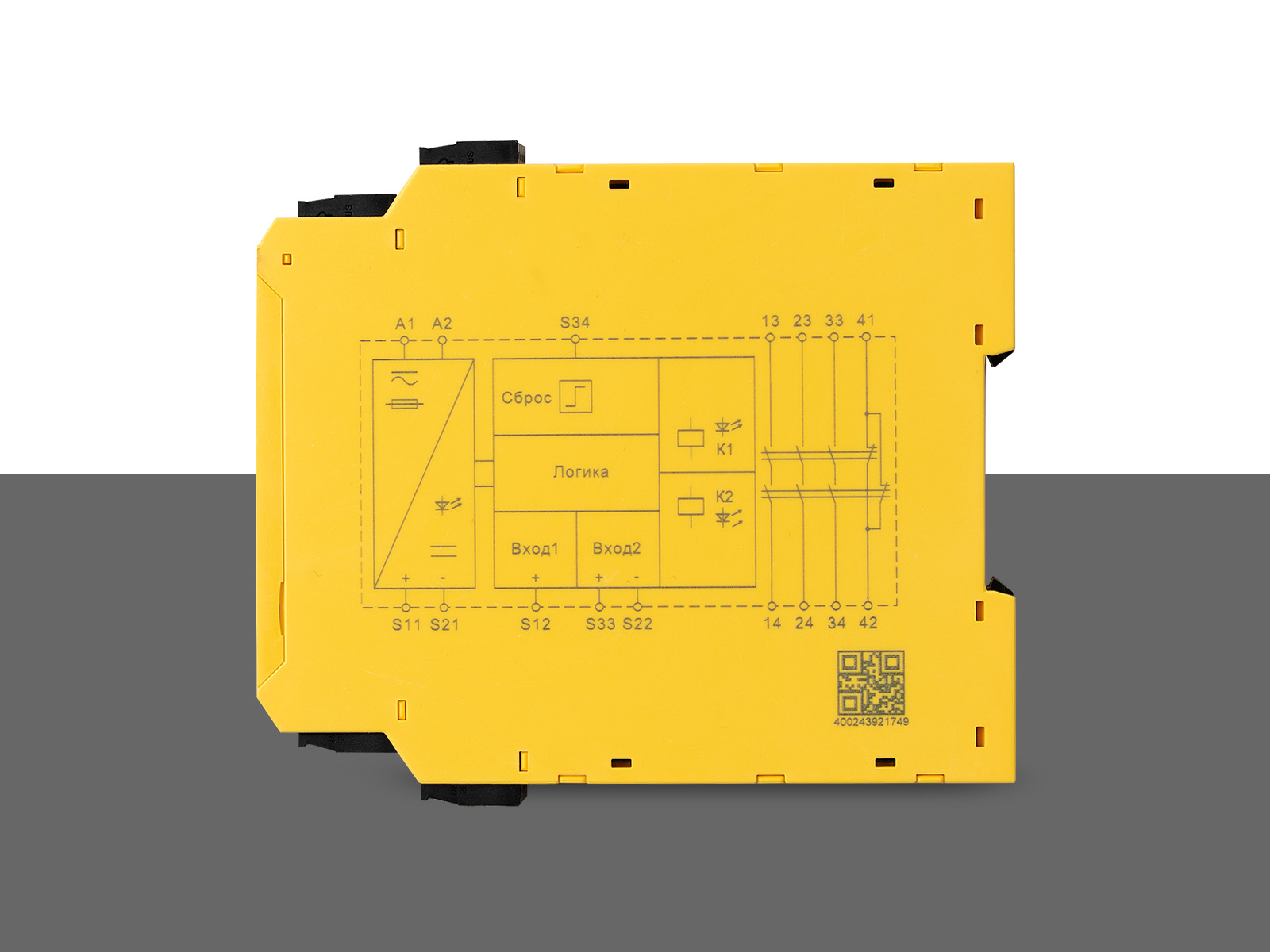
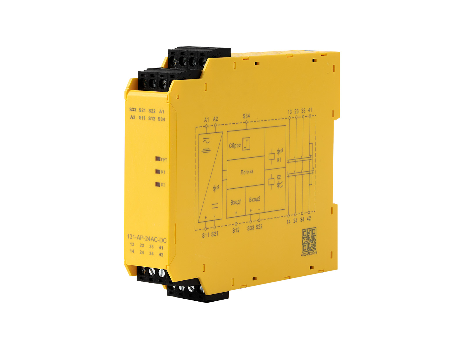
| Main parameters | |
| Voltage range, V | ~/=24 |
| Voltage tolerances, V | 0,85… 1,1 |
| Frequency, Hz | Frequency, Hz 50… 60 |
| Heat output, W | ≤ 2.2 at =24 V, ≤ 5.4 at ~24 V |
| Current consumption at =24 V, mA | ≤ 50 |
| Cable resistance, Ohm | 15 |
| Input devices | Emergency stop button, safety gate, PNP safety light curtain |
| Signal type | 3no + 1nz |
| Contact type | forced management |
| Contact material | AgSnO2 + 0.2 μm Au |
| Load characteristics | AC-15: 5 A / 230 V; DC-13: 5 A / 24 V |
| Fuse characteristics | 10 A gL/gG(no), 6 A gL/gG(no) |
| Response time, ms | Auto: ≤ 300, manual: ≤ 150 |
| Opening, ms | Auto stop: ≤ 30, power failure: ≤ 100 |
| Recovery time, ms | Auto stop: ≤ 30, power failure: ≤ 100 |
| Power interruption, ms | 20 |
| Electromagnetic compatibility | IEC/EN 80947, IEC 61326-3-1, IEC/EN 61000-6-2, IEC/EN 61000-6-4 |
| Nominal insulation voltage , V AC |
250 |
| Nominal pulse voltage, V | 6000 (1.2/50 µs) |
| Dielectric strength, V | 1500 (within 1 min) |
| Gaps and leaks | According to IEC 80947-1 |
| Vibration, Hz | 10…55 (0.35 mm) |
| Overvoltage category | III |
| Degree of pollution | 2 |
| Degree of dust and moisture protection | IP20 |
| Operating temperature, °C | -20…. +60 |
| Storage temperature, °C | -40…. +80 |
| Altitude above sea level, m | ≤ 2000 |
| Number of operations, cycles | 10 x 106 |
| Security parameters | |
| Safety Integrity Level (SIL) | 3 |
| Average diagnostic coverage (DC avg), % | 99 |
| Mean time to failure (MTTFD), years | 164 |
| Hardware Fault Tolerance (HFT) | 1 |
| Safe failure rate (SFF), not less than, % | 99 |
| Average probability of dangerous failure on demand (PFDavg/PTI) | 1,29×10⁻⁵ |
| Probability of failure per hour (PFH), 1/h | 1,49×10⁻¹⁰ |
| Stop category | 0 |
| Connection diagram | |
 |
|

Input: "Emergency stop", 1-channel.
Without short-circuit signaling on contacts.
Automatic reset.
Output: 3 NO + 1 NC (auxiliary).

Input: "Emergency stop", 2-channel.
Without short-circuit signaling on contacts.
Manual reset.
Output: 3 NO + 1 NC (auxiliary).

Input: "Emergency stop", 2-channel.
With short-circuit signaling on contacts.
Automatic reset, EDM function*.
Output: 3 NO + 1 NC (auxiliary).

Input: "Emergency stop", 2-channel.
With short-circuit signaling on contacts.
Manual reset, EDM function*.
Output: 3 NO + 1 NC (auxiliary).

Input: PNP light curtain signal.
With short-circuit signaling using a ZECHA**.
Manual reset, EDM function*.
Output: 3 NO + 1 NC (auxiliary).
*EDM (External Device Monitor) is a device check for external devices, i.e., detecting faults in external devices (e.g., contact welding) in hazardous parts of electrical machines. External devices are typically safety relays or contactors. The device continuously monitors whether a specified voltage has been applied to the external relay's control input line and blocks it in the event of an error. If the response delay of the monitored relay exceeds 300 ms, it is considered an error.
Overall, the EDM function of a safety relay is an important safety protection function. It monitors the status of external equipment in real time and promptly detects and reports equipment failures to ensure that it can play a protective role in hazardous situations. This function is especially important in industrial scenarios where worker safety must be ensured while simultaneously performing precision machining.
**- Electro-sensitive protective equipment (ESPE) is a set of devices and/or components that act together to protect or detect a safety-related part of a system.
The safety-related electronic control system consists of at least:
- a sensing device;
- control/monitoring devices;
- switching devices for the output signal and/or information interface related to safety.
Drag files here
CAD " GORELTEX ", questionnaires, necessary documents
Head office and production site
Sales office
Sales office
Sales office and production site
Sales office
Sales office

